Kollmorgen Support Network

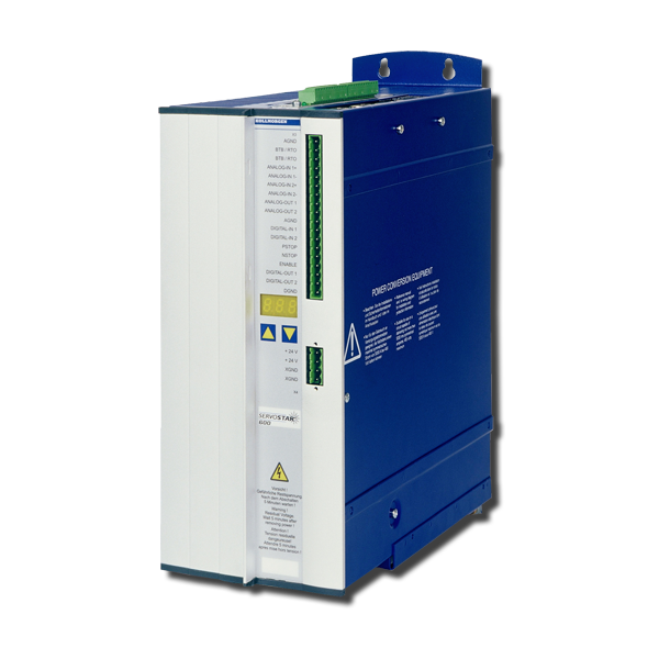
S600

This servo amplifier is comprised of a three-phase power supply and a high-performance control unit housed in a single enclosure. This servo amplifier is available in 230VAC-480VAC, 1.5-20 Amp models.

NOTEThe S640 and S670 models (high-power models) have been discontinued.

Interfaces

Digital / Analog I/OsPosition Output
(encoder emulation)
MultiFieldbusMultiFeedback
  • 2 programmable analog inputs
  • 4 programmable digital inputs
  • 2 programmable digital outputs
  • 14 digital inputs and 8 outputs with expansion card I/O-14/08
  • RS232 service channel
  • Emulation incremental encoder
  • Emulation absolut encoder SSI (binary or Gray)

Digital I/O Features

 Max. input FrequencyHardware DelaySoftware Delay
Digital Input 1/2100 Khz (Ser.No. > 220000)
otherwise 10 Khz
< 5 µs
< 50 µs for max. input frequency 10Khz
Depends on the selected functionality
Digital Input PSTOP/NSTOP10 Khz< 50µsDepends on the selected functionality
Digital Output 1/2-< 50 µs< 5 ms

Analog I/O Features

 Hardware Filter ConstantSoftware Delay
Analog Input 1150 µs250 µs + Selected Delay AVZ1
Analog Input 250µs250 µs Speed Control 125 µs Torque Control
Analog Output1 ms250 µs

Hardware Expansions

Firmware Reference Table

old Firmware Version
Hardware Rev. <5.30
Firmware Version
Hardware Rev. 5.30
new Firmware Version
Hardware Rev. 5.40
1.xx9.509.50_nd0
2.xx9.509.50_nd0
3.xx9.509.50_nd0
4.xx8.508.70_nd0
5.xx9.509.50_nd0
5.819.008.70_nd0
6.xx8.508.70_nd0
7.xx9.509.50_nd0
8.00...8.158.508.70_nd0

S600 Hardware Revision Number

S601...620

Hardware RevisionFirmware VersionDateRemarksExport Classification
05.105.76 - 5.802006-04Starting versionAL-3A225
05.20

5.81 - 5.99

7.05 - 7.99

2009-12CAN controller newAL-3A225

6.86 - 6.99

8.00 - 8.49

2009-12with EtherCAT, BiSSAL-3A225
05.30>= 9.002014-02PCB update, standardAL-3A225
>= 8.502014-02PCB update, with EtherCAT, BiSSAL-3A225
05.40>= 9.00_ND12014-12Dual use, new data structureAL-3A225
>= 8.50_ND12014-12Dual use, new data structureAL-3A225
05.40>= 9.00_ND02014-12Non Dual use, new data structure-
>= 8.50_ND02014-12Non Dual use, new data structure-

S640/670

Hardware RevisionFirmware VersionDateRemarksExport Classification
02.06>= 5.992006-04Starting versionAL-3A225
02.10>= 7.762009-12CAN controller newAL-3A225
>= 6.862009-12with BiSS evaluationAL-3A225
02.20>= 7.76_ND12014-12Dual use, new data structureAL-3A225
>= 6.86_ND12014-12Dual use, new data structureAL-3A225
02.20>= 7.76_ND02014-12Non Dual use, new data structure-
>= 6.86_ND02014-12Non Dual use, new data structure-
Mensagem de Erro F09 Portuguese, Brazil
Giuliano…
Mensagem de Erro F08 Portuguese, Brazil
Giuliano…
Mensagem de erro F07 Portuguese, Brazil
Giuliano…
Mensagem de Erro F06 Portuguese, Brazil
Giuliano…
Mensagem de erro F05 Portuguese, Brazil
Giuliano…
Códigos do Display LED para S700, S300, S600, S400 Portuguese, Brazil
Leonardo…
Mensagem de Erro F04 Portuguese, Brazil
Giuliano…
Mensagem de Erro F03 Portuguese, Brazil
Giuliano…
Mensagem de erro F02 Portuguese, Brazil
Giuliano…
What causes the error message F14?

Fault in the power output stage. Can also be triggered by a wrong or faulty motor cable, if the screen of the motor cable is not connected or if the motor is feaulty. Refer to page Error Message F14.

The servo amplifier does not react to the incremental set point at the AquadB input. Why doesn't the electronic gearing work?

Possible reasons:

  • OPMODE <> 4
  • AquadB interface not switchwed to input
  • Servo amplifier disabled (Enable=0) 
  • Limit switch active (warning n10 or n11 in the LED display)
Which delay time can occur during Master / Slave operation?

Incremental signals (AquadB): processing time in the servo amplifier (FPGA) are in "ns" range. Slave reaction time ±62,5µs (current control task).

How can I set up camming?

The servo amplifiers use position registers to define cams. The status of the registers are sent as cams to one or two digital outputs by a predefined function. Refer to page Setup of Camming S300-S700 or Setup of Camming S400-S600. You can define up to 8 cams for a digital output with S300/S700.

I changed a parameter with the GUI and saved it to the EEPROM but after restarting the amplifier the old value was used.

Parameters may be changed via a fieldbus (during the initialization) or by a defined command sequence via the digital inputs (INxMODE 30).

Which settings are required for operating an induction machine?
What does Hardware Revision mean on the nameplate of the servo amplifier?

The Hardware Revision defines the development status of the servo amplifier. The same number can be found on the cover page of the instructions manual. Refer to page Hardware Revision Number.

What do I have to consider when using a residual current protective device (RCD) in a servo system?
Is it possible to use motors with a feedback system without commutation information as a primary feedback.

Yes. A Wake & Shake function determines the absolute position of the permanent Magnets in relationship to the stator windings. See page Wake and Shake.