


 Home >
 Knowledge Base >
 FAQs >
 Downloads >
Setup of Camming S300, S700
Valid for S300, S700
There are two possible procedures to define camming: with the setup software or by ASCII commands with a terminal software.
Setup with Setup Software
Setting up the camming functionality with position registers is very simply when using the setup software.
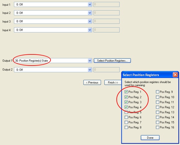
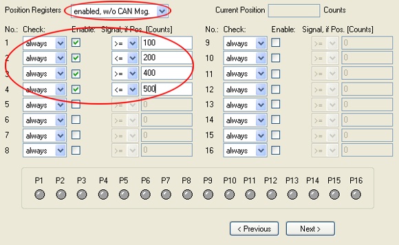
By setting position registers a camming application can be realized. In the example below 2 cams are set for a distance from 100 to 200 and 400 to 500. With Digital Out 1 the position register status is monitored. (parameter POSRSTAT).
Setup of the output function (screen page Digital I/O) and definition of the status mask:
Setup Position Registers (screen page Position Registers):
Saving the setting to the EEPROM finishes the configuration process.
Setup with Terminal
Used ASCII command
- P1...P16 = Position register 1 … 16
- WPOS
WPOS=0 position register disabled
WPOS=1 position register enabled, no CAN message
WPOS=2 position register enabled, CAN message when status changes (this setting is possible via CAN bus only) - WPOSE
Bit=0 the position register is not supervised
Bit=1 the position register is supervised - WPOSP
Bit=0 message when position is exceeded
Bit=1 message when position falls below - WPOSX
Bit=0 position is permanently supervised
Bit=1 position is supervised once
While creating the position message the corresponding Enable Bit (WPOSE) is set to 0, to disable supervision of the position register. - O1MODE =30 logical AND between POSRSTAT and O1TRIG
- O2MODE =30 logical AND between POSRSTAT and O2TRIG
- O1TRIG mask for O1MODE
- O2TRIG mask for O2MODE
- POSRSTAT status information for position register P1...P16 (read only!)
Position registers P1...P16 are used to define the switch on and switch off limits for the cams. The values must be filled in logically increasing. For executing the function, the cariable WPOS must be set to a value > 0 (WPOS = 1, see above).
Activating Position Registers P1 ... P16
The position registers are activated with the bit variable WPOSE. Value 0 means no supervision of the register Px, value 1 means active.
Bit0 = P1, Bit1 = P2, ... Bit15 = P16.
When does a message arrive from register Px
Variablen WPOSP defines, when a message is sent by a position register. Value 0 sets the corresponding status bis when the Px value is exceeded, value 1 enables the status bit when the actual value fall below the Px limit.
Bit0 = P1, Bit1 = P2, ... Bit15 = P16.
Position Supervision Frequency
is defined by the variable WPOSX. Value 0 means continuous supervising, value 1 means one time only.
Bit0 = P1, Bit1 = P2, ... Bit15 = P16.
Output of CAM function to digital Outputs 1 or 2
The matching variable OxMODE must be set to function 30 and the matching trigger variable OxTRIG must be set. Several cams can be assigned to one output, this depends on the variable =xTRIG only.
After changing this parameter the servo amplifier must be switched off and on again.
ASCII command POSRSTAT
All position messages are saved in a status register, independant from digital output functions, and can be read out via the serial interface as well as via CAN-/PROFIBUS- interface.
Application example
On a traverse the digital output 1 shall work like a cam from 200 to 240 and digital output 2 from 800 to 900:
The settings below can be done in the terminal screen of the setup software:
| ASCII Command | Description |
| K | Disable amplifier by software |
| P1 200 | Cam 1 - switch on limit |
| P2 240 | Cam 1 - switch off limit |
| P3 800 | Cam 2 - switch on limit |
| P4 900 | Cam 2 - switch off limit |
| WPOS 1 | Enable Register |
| WPOSE 15 | supervise P1 ... P4 (0000 1111) |
| WPOSX 0 | Permanent supervision of the registers |
| WPOSP 10 | P1 and P3 = 0, message when exceeding position, P2 and P4 = 1, messsage when falling below position. (0000 1010) |
| O1MODE 30 | Set Output 1 to function 30 |
| O1TRIG 3 | AND mask for P1 and P2 (0000 0011) |
| O2MODE 30 | Set output 2 to function 30 |
| O2TRIG 12 | AND mask for P3 and P4 (0000 1100) |
| SAVE | Save parameters |
| COLDSTART | Activate new configuration (reboot) |
