Kollmorgen Support Network

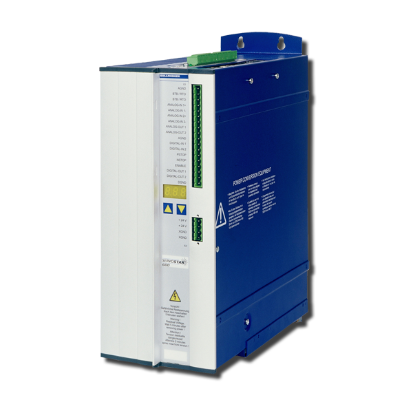
S600

This servo amplifier is comprised of a three-phase power supply and a high-performance control unit housed in a single enclosure. This servo amplifier is available in 230VAC-480VAC, 1.5-20 Amp models.

NOTEThe S640 and S670 models (high-power models) have been discontinued.

Interfaces

Digital / Analog I/OsPosition Output
(encoder emulation)
MultiFieldbusMultiFeedback
  • 2 programmable analog inputs
  • 4 programmable digital inputs
  • 2 programmable digital outputs
  • 14 digital inputs and 8 outputs with expansion card I/O-14/08
  • RS232 service channel
  • Emulation incremental encoder
  • Emulation absolut encoder SSI (binary or Gray)

Digital I/O Features

 Max. input FrequencyHardware DelaySoftware Delay
Digital Input 1/2100 Khz (Ser.No. > 220000)
otherwise 10 Khz
< 5 µs
< 50 µs for max. input frequency 10Khz
Depends on the selected functionality
Digital Input PSTOP/NSTOP10 Khz< 50µsDepends on the selected functionality
Digital Output 1/2-< 50 µs< 5 ms

Analog I/O Features

 Hardware Filter ConstantSoftware Delay
Analog Input 1150 µs250 µs + Selected Delay AVZ1
Analog Input 250µs250 µs Speed Control 125 µs Torque Control
Analog Output1 ms250 µs

Hardware Expansions

Firmware Reference Table

old Firmware Version
Hardware Rev. <5.30
Firmware Version
Hardware Rev. 5.30
new Firmware Version
Hardware Rev. 5.40
1.xx9.509.50_nd0
2.xx9.509.50_nd0
3.xx9.509.50_nd0
4.xx8.508.70_nd0
5.xx9.509.50_nd0
5.819.008.70_nd0
6.xx8.508.70_nd0
7.xx9.509.50_nd0
8.00...8.158.508.70_nd0

S600 Hardware Revision Number

S601...620

Hardware RevisionFirmware VersionDateRemarksExport Classification
05.105.76 - 5.802006-04Starting versionAL-3A225
05.20

5.81 - 5.99

7.05 - 7.99

2009-12CAN controller newAL-3A225

6.86 - 6.99

8.00 - 8.49

2009-12with EtherCAT, BiSSAL-3A225
05.30>= 9.002014-02PCB update, standardAL-3A225
>= 8.502014-02PCB update, with EtherCAT, BiSSAL-3A225
05.40>= 9.00_ND12014-12Dual use, new data structureAL-3A225
>= 8.50_ND12014-12Dual use, new data structureAL-3A225
05.40>= 9.00_ND02014-12Non Dual use, new data structure-
>= 8.50_ND02014-12Non Dual use, new data structure-

S640/670

Hardware RevisionFirmware VersionDateRemarksExport Classification
02.06>= 5.992006-04Starting versionAL-3A225
02.10>= 7.762009-12CAN controller newAL-3A225
>= 6.862009-12with BiSS evaluationAL-3A225
02.20>= 7.76_ND12014-12Dual use, new data structureAL-3A225
>= 6.86_ND12014-12Dual use, new data structureAL-3A225
02.20>= 7.76_ND02014-12Non Dual use, new data structure-
>= 6.86_ND02014-12Non Dual use, new data structure-
Mensagem de Erro F27 Portuguese, Brazil
Giuliano…
Mensagem de Erro F26 Portuguese, Brazil
Giuliano…
Mensagem de Erro F25 Portuguese, Brazil
Giuliano…
Mensagem de Erro F24 Portuguese, Brazil
Giuliano…
Mensagem de Erro F23 Portuguese, Brazil
Giuliano…
Mensagem de Erro F22 Portuguese, Brazil
Giuliano…
Mensagem de Erro F21 Portuguese, Brazil
Giuliano…
Mensagem de Erro F20 Portuguese, Brazil
Giuliano…
Mensagem de Erro F19 Portuguese, Brazil
Giuliano…
If the I2T value is shown in the S600 oscilloscope then the units are increments. What's the reason for that?

The I2t resolution is built from: 

Scaling i2t = 688537600 in the scope is 100% I2T if ICONT = DICONT of the amplifier. 

If ICONT is 0.5 DICONT for example, then the value is 688537600 * 0.5 * 0.5.

If FOLDTIME differs from the default value 16 ms for example, this has influence to the calculation as well: 

688537600 * (ICONT/ DICONT)^2 * FOLDTIME / 16

How many slave S600s can be connected to one master S600 (electronic gearing, X5)?

You can operate up to 15 slaves with one master.

How long can the S600 be charged with more than its rated output current?

t = -17.4 * ln (1.0 - SQR(ICONT/I))

Example:
Inenn = 20 A (Typ S620)
Iist = 30 A
t = -17.4 * ln (1.0 - SQR(20/30))
t = -17.4 * ln (1.0 - 4/9)
t = -17.4 * ln (5 / 9)
t = -17.4 * (-0.587787)
t = 10.22 sec

How can I use the AS Option?
  1. Parameters to set
    STOPMODE 1
    (0 default)
    If the drive is disabled, the amplifier switches to velocity mode and breakes with the ramp DECDIS. When the velocity VEL0 is reached, the power stage becomes disabled.
    ACTFAULT 1
    (1 default)
    If an error occurs, the amplifier switches to velocity mode and breakes with the ramp DECSTOP. When the velocity VEL0 is reached, the power stage becomes disabled. Exceptions are amoung others overvoltage and motor phase fault. In these cases a procedur like this would case additional problems.
    O1MODE 21 High with active power stage / Low with disabled power stage
    EMRTO
    (5000 Default)
    If the drive does not brake or the velocity does not reach VELO then the power stage will disable after this time.

    If setting of these time is too small, then the motor will never be braked down. For this reason DECDIS and DECSTOP must be realistic values and EMRGTO must be larger than DECDIS and DECSTOP.

  2. Process: switch off

    Disable the drive - The motor will be braked with DECDIS. Power stage disables. Output 1 switches to low.
    Switch 24V to the AS Enable input.
     
  3. Process: restart

    Switch off 24V from AS Enable.
    Switch Enable (HW and SW).
Can I reduce the fan noise?

We offer an option card for the option slot in the S610...620 an. The device must be opened for the installation of this card, therefore the customer can't do that by himself without loosing warranty.

The card ist wired to the fam terminal in the amplifier and the fan is wired to the option card.

Why does the Multidrive communication not work?
  • Multidrive is not selected in the setup software
  • Master axis does not have ADDR 8
  • Different CAN baud rates are set
What is the current supply at the SinCos encoder interface?

At connector X1 there are 5V/150 mA available. These values are nominal even at maximum load. If a higher current is required, we offer an external power supply (350 mA) with a 1m cable. See instructions manual.

What are the maximum ramp times?

The maximum ramp time in a motion task can be calculated by: 

t{ms} = 140/32 x nsetp with PRBASE 16, 20 oder 
t{ms} = 140/32 x 16 x nsetp with PRBASE = 24.

Reduction while braking: tmax = 8000ms
Speed controller: t{ms} = 140 x 128 x n{rpm}

Is it possible to communicate with several servo amplifiers simultaneously via RS232 (Multidrive)?

Serial Communication via RS232 physically works with one amplifier only, but if you have connected several amplifiers via CAN bus to the "first" amplifier, you can communicate with all of them via RS232. This works either with the setup software (Multidrive must be selected) or with e terminal program (see page Multidrive Communication via RS232).