Kollmorgen Support Network

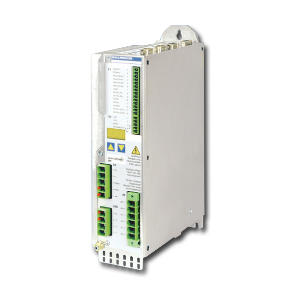
S300

This servo amplifier is comprised of a three-phase power supply and a high-performance control unit housed in a single enclosure. This single axis servo amplifier is available in 110VAC-480VAC, 1,5-10A models.

  • MultiFeedback, MultiFieldbus
  • EMC - Mains Filter and Brake Resistor internally
  • Safety Function STO, SIL2, PLd

See S300 & S700 Errors and Warnings for a comprehensive list of faults.

S300 Hardware Revision Number

Hardware Revision Firmware Version Date Remarks Export Classification
02.01 2.18 to 3.74 2006-04 Starting version AL-3A225
02.10 (03.01) 3.75 to 3.99 2010-05 AS->STO, new approval AL-3A225
04.00 5.18 - 5.99 2011-05 New CPU AL-3A225
04.10 5.18_ND1 - 5.99_ND1 2014-12 Dual use, new data structure AL-3A225
04.10 5.18_ND0 - 5.99_ND0 2014-12 Non Dual use, new data structure -
04.20 >=6.00_ND1* 2017-04 Dual use, single-cable motor Connection possible, memory increased AL-3A225
04.20 >=6.00_ND0* 2017-04 Non Dual Use, single-cable motor Connection possible, memory increased -
For Firmewaredowngrade < 5.45 please contact your service partner
 
Códigos de Falha Portuguese, Brazil
Giuliano…
Mensagem de Erro F32 Portuguese, Brazil
Giuliano…
Mensagem de Erro F31 Portuguese, Brazil
Giuliano…
Mensagem de Erro F30 Portuguese, Brazil
Giuliano…
Mensagem de Erro F28 Portuguese, Brazil
Giuliano…
Mensagem de Erro F27 Portuguese, Brazil
Giuliano…
Mensagem de Erro F26 Portuguese, Brazil
Giuliano…
Mensagem de Erro F25 Portuguese, Brazil
Giuliano…
Mensagem de Erro F24 Portuguese, Brazil
Giuliano…
The servo amplifier does not react to the incremental set point at the AquadB input. Why doesn't the electronic gearing work?

Possible reasons:

  • OPMODE <> 4
  • AquadB interface not switchwed to input
  • Servo amplifier disabled (Enable=0) 
  • Limit switch active (warning n10 or n11 in the LED display)
Which delay time can occur during Master / Slave operation?

Incremental signals (AquadB): processing time in the servo amplifier (FPGA) are in "ns" range. Slave reaction time ±62,5µs (current control task).

How can I set up camming?

The servo amplifiers use position registers to define cams. The status of the registers are sent as cams to one or two digital outputs by a predefined function. Refer to page Setup of Camming S300-S700 or Setup of Camming S400-S600. You can define up to 8 cams for a digital output with S300/S700.

Positioning errors with AKM1 motors

Low rotor inertia is the source for this problem, ironless linear motors show a similar behavior.

Solution for drives with S300/S700 servo amplifiers: 

How can an external zero sensor for homing be determined?

Refer to page External zero pulse

Is it possible to switch over parameters during operation?

Yes, either sequential with the function InxMODE=30 or with parallel switch over of two predefined parameter sets. Refer to page Switching over parameter sets.

What is a Bode Plot used for?

Bode Plot is a process to analyze frequency behavior of the drive. See pages Tuning - Built in Frequency Analysis and Bode Diagram

Is it possible to operate DC motors?

Yes, that's possible with S300 and S700. See page Operating DC motors S300-S700.

I changed a parameter with the GUI and saved it to the EEPROM but after restarting the amplifier the old value was used.

Parameters may be changed via a fieldbus (during the initialization) or by a defined command sequence via the digital inputs (INxMODE 30).