Kollmorgen Support Network

S400

Discontinued

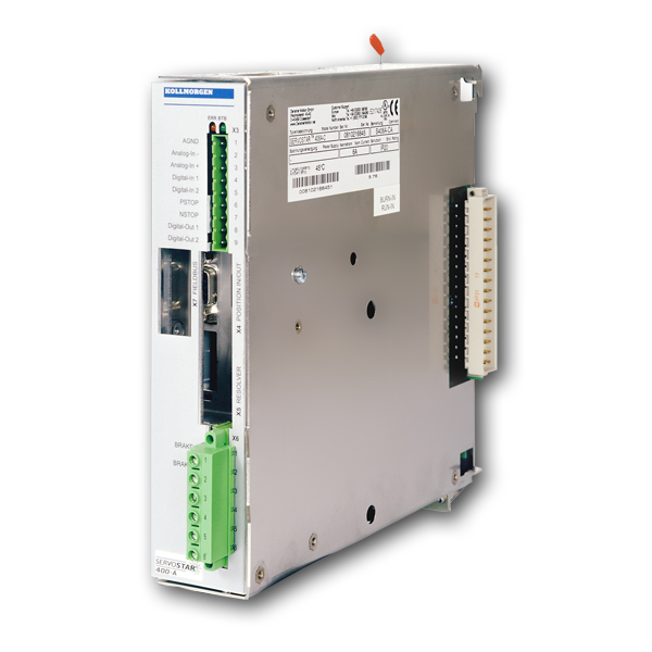
This servo amplifier is comprised of a three-phase power supply and a high-performance control unit housed in a single enclosure. This servo amplifier is available in 115VAC-400VAC, 3 or 6A models.

Part Number Scheme

Options

Software

Interfaces

Digital / Analog I/Os Position output (encoder emulation MultiFieldbus MultiFeedback
  • 1 programmable analog input
  • 4 programmable digital inputs
  • 2 programmable digital outputs
  • RS232 service channel

S400 Hardware Revision Number

Hardware Revision Firmware Version Date Remarks Export Classification
02.03
 
>= 5.76 2006-04 Starting version AL-3A225
>= 6.68   with BiSS evaluation AL-3A225
03.03
 
>= 5.76 2008-06 heat sink optimized AL-3A225
>= 6.68   with BiSS evaluation AL-3A225
03.10 >= 7.76 2009-12 CAN controller new AL-3A225
>= 6.86 2009-12 with BiSS evaluation AL-3A225
03.20 >= 7.76_ND1 2014-12 Dual use, new data structure AL-3A225
>= 6.86_ND1 2014-12 Dual use, new data structure AL-3A225
03.20 >= 7.76_ND0 2014-12 Non Dual use, new data structure -
>= 6.86_ND0 2014-12 Non Dual use, new data structure -
Mensagem de Erro F25 Portuguese, Brazil
Giuliano…
Mensagem de Erro F24 Portuguese, Brazil
Giuliano…
Mensagem de Erro F23 Portuguese, Brazil
Giuliano…
Mensagem de Erro F22 Portuguese, Brazil
Giuliano…
Mensagem de Erro F21 Portuguese, Brazil
Giuliano…
Mensagem de Erro F20 Portuguese, Brazil
Giuliano…
Mensagem de Erro F19 Portuguese, Brazil
Giuliano…
Mensagem de Erro F18 Portuguese, Brazil
Giuliano…
Mensagem de Erro F17 Portuguese, Brazil
Giuliano…
How can I start communication to an axis module, if communication is not possible after boot?

Start Hiperterminal: 

with no response; 
„\“ type until the command is accepted, then switch over with 
„\ 0“ to the master; 
type SCANX and 
Prompt „-->“ wait; 

Now communication is possible.

How can I setup indexing via digital inputs?

See the page Indexing

How can I basically setup the current control parameters dependent on the used motor?

MLGQ = 12 * L{mH} * DIPEAK {A} / 1000
KTN 0.6

Example:
S603 --> Dipeak 6A
L=3mH - Motor inductance
MLGQ = 12 * L * DIPEAK / 1000 = 0.216
KTN 0.6

Leave all other values unchanged.

Is it possible to drive High Frequency Motors (Spindles) with the servo amplifiers?

Yes. With the help of pole number setting. Refer to page Tuning - High Frequency Spindles S300-S700.

Which acceleration and deceleration ramps are used in motion task series?

This can be selected on the screen page "Motion Task Parameters". Refer to page Motion Task Series.

What does P01, E01 or -S- mean in the display?

P01: 1A power stage, mains supply voltage switched on, power stage disabled
E01: 1A power stage, mains supply voltage switched on, power stage enabled
-S-: STO Enable input is not connected or no 24V signal is applied

Refer to page LED Display Codes S300-S700.

How can I protect the parameter set against write access?

Yes, you can activate a password protection. Refer to page Password Protection.

What causes the error message F14?

Fault in the power output stage. Can also be triggered by a wrong or faulty motor cable, if the screen of the motor cable is not connected or if the motor is feaulty. Refer to page Error Message F14.

The servo amplifier does not react to the incremental set point at the AquadB input. Why doesn't the electronic gearing work?

Possible reasons:

  • OPMODE <> 4
  • AquadB interface not switchwed to input
  • Servo amplifier disabled (Enable=0) 
  • Limit switch active (warning n10 or n11 in the LED display)