


 Home >
 Knowledge Base >
 FAQs >
 Downloads >
Servo Drive FAQs
Following are a series of Frequently Asked Questions relating to S300, S400, S600, and S700 drives.
Frequently Asked Questions
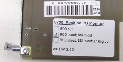
The card exists with different versions, visible on a label on the card's PCB.
With the current version (Nov. 08) "ROD in/out; SSI in/out" is marked on the label and the S700 needs at least Firmware 3.50.
If "ROD out" is marked or no label exists, you have an older version, which can only be operated with an older firmware (3.06). Updating the card to the current version is possible at the manufacturer site.
A memory card is plugged but there is a problem to access the card. Remove and insert the card again. In case that the setup software is online, the message "Please re - insert the memory card" appears. More information to memory cards can be found on page Memory Card.
SD Card is not FAT32 formatted and is not usable therefore. See page LED Display.
- faulty motion task number
- faulty motion task checksum
- table motion task without matching profile table
- absolut target position outside of modulo range (with modulo axes only)
- target position outside of software limit switches
- internal overflow while calculating motion task ramps/position/speed
- (invalid conditions for profile table motion task change on-the-fly)
The ASCII command MOVE works in OPMODE 8 (Motion tasks) and in OPMODE 4 (electrical gearing)!
The difference between these devices is the STO concept (single channel - dual channel). The new second STO input is on X4A pin 3. This pin has been used as XGND connection with the old drive. So the drive has no 24V supply voltage now. Please see the page Safety Concept S700.
In case of single line supply the Maximum current values are calculated with the following formula (Rotary axis)
IPeakMax = Max. Single Line Peak Power * 60 / (2 * 3.14 * MKT * VLIM)
IContMax = Max. Single Line Nominal Power * 60 / (2 * 3.14 * MKT * VLIM)
In case of high MKT and high Motor Speed the power must be limited to prevent capacitors from being destroyed.
Example for S712:
IPeakMax = 3300 Watts * 60 Sec / (2 * 3.14 * 5 Nm/A * 14648 UPM) = 0.43 A
IContMax = 2200 Watts * 60 Sec/ (2 * 3.14 * 5 Nm/A * 14648 UPM) = 0.29
DC supply voltage is smaller than VBUSMIN
F22 occurs in case of approximately
S640: current peak > 56A
S670: current peak > 112A
S640: current peak > 163A
S670: current peak > 326A
EtherCAT works from firmware version 6.43. Firmware Versions 7.xx cannot be used.
SynqNet requires always a special firmware version. Please ask the Kollmorgen Support for this file.
Fan on:
Heat sink temperature > 65°C or environment temperature > 58°C or brake power > 30 Watts
Fan off:
Heat sink temperature < 60°C and environment temperature < 55°C and brake power < 20 Watts
1 million data saves or 20 years
For the whole S600 family the value is 290,000 hours.
No, the firmware version for S600 with serial number < 220.000 must be < 4.00
The I2t resolution is built from:
Scaling i2t = 688537600 in the scope is 100% I2T if ICONT = DICONT of the amplifier.
If ICONT is 0.5 DICONT for example, then the value is 688537600 * 0.5 * 0.5.
If FOLDTIME differs from the default value 16 ms for example, this has influence to the calculation as well:
688537600 * (ICONT/ DICONT)^2 * FOLDTIME / 16
You can operate up to 15 slaves with one master.
t = -17.4 * ln (1.0 - SQR(ICONT/I))
Example:
Inenn = 20 A (Typ S620)
Iist = 30 A
t = -17.4 * ln (1.0 - SQR(20/30))
t = -17.4 * ln (1.0 - 4/9)
t = -17.4 * ln (5 / 9)
t = -17.4 * (-0.587787)
t = 10.22 sec
- Parameters to set
STOPMODE 1
(0 default)If the drive is disabled, the amplifier switches to velocity mode and breakes with the ramp DECDIS. When the velocity VEL0 is reached, the power stage becomes disabled. ACTFAULT 1
(1 default)If an error occurs, the amplifier switches to velocity mode and breakes with the ramp DECSTOP. When the velocity VEL0 is reached, the power stage becomes disabled. Exceptions are amoung others overvoltage and motor phase fault. In these cases a procedur like this would case additional problems. O1MODE 21 High with active power stage / Low with disabled power stage EMRTO
(5000 Default)If the drive does not brake or the velocity does not reach VELO then the power stage will disable after this time. If setting of these time is too small, then the motor will never be braked down. For this reason DECDIS and DECSTOP must be realistic values and EMRGTO must be larger than DECDIS and DECSTOP.
- Process: switch off
Disable the drive - The motor will be braked with DECDIS. Power stage disables. Output 1 switches to low.
Switch 24V to the AS Enable input.
- Process: restart
Switch off 24V from AS Enable.
Switch Enable (HW and SW).
We offer an option card for the option slot in the S610...620 an. The device must be opened for the installation of this card, therefore the customer can't do that by himself without loosing warranty.
The card ist wired to the fam terminal in the amplifier and the fan is wired to the option card.
- Multidrive is not selected in the setup software
- Master axis does not have ADDR 8
- Different CAN baud rates are set
At connector X1 there are 5V/150 mA available. These values are nominal even at maximum load. If a higher current is required, we offer an external power supply (350 mA) with a 1m cable. See instructions manual.
The maximum ramp time in a motion task can be calculated by:
t{ms} = 140/32 x nsetp with PRBASE 16, 20 oder
t{ms} = 140/32 x 16 x nsetp with PRBASE = 24.
Reduction while braking: tmax = 8000ms
Speed controller: t{ms} = 140 x 128 x n{rpm}
Serial Communication via RS232 physically works with one amplifier only, but if you have connected several amplifiers via CAN bus to the "first" amplifier, you can communicate with all of them via RS232. This works either with the setup software (Multidrive must be selected) or with e terminal program (see page Multidrive Communication via RS232).
If the motor has a Resolver feedback, the page Setup of unknown motors describes the process.
Limit Ipeak and make sure, that no damage can occur even if the motor runs off.
Example 1: The motor type is not listed at all:
- Select FBTYPE = 4, SAVE, COLDSTART
- Read MPHASE, set MNUMBER = 0, SAVE; HSAVE and COLDSTART.
After rebooting, check MPHASE. If MPHASE no longer matches the original value, the source value must be set. Now all the motor parameters have to be determined.
Example 2: The motor is listed as a motor with resolver:
- Select FBTYPE = 4, SAVE, COLDSTART
- Read MPHASE, set MNUMBER = 0, SAVE; HSAVE and COLDSTART.
- FBTYPE = 0, SAVE, and COLDSTART. Then select the appropriate resolver motor and save with SAVE, then COLDSTART.
- FBTYPE = 4, SAVE and COLDSTART.
After rebooting, check MPHASE. If MPHASE no longer matches the original value, the source value must be set.
7 axes additional to the master axis.
20µs with a jitter of 1µs.
The moment of the position latching is determined. With the next cycle of the position controller the (T=250µs) the latch position is calculated. High speed deviation in this cycle can lead to determination errors.
Presumption is FW >7.22.
DRVCFG2 = -2147483648 (= -2^31, set bit 31).
Start Hiperterminal:
with no response;
„\“ type until the command is accepted, then switch over with
„\ 0“ to the master;
type SCANX and
Prompt „-->“ wait;
Now communication is possible.
See the page Indexing
MLGQ = 12 * L{mH} * DIPEAK {A} / 1000
KTN 0.6
Example:
S603 --> Dipeak 6A
L=3mH - Motor inductance
MLGQ = 12 * L * DIPEAK / 1000 = 0.216
KTN 0.6
Leave all other values unchanged.
Set BUSP1 to 1 and finalize the configuration change with SAVE and COLDSTART.
Background: Bit 30 (COB-ID Setting for Tx-PDO) is supervised since Firmware 2.51. The amplifier sets the bit and expects the COB identifier is written with set bit 30, too (means: no RTR request of TX-PDOs is possible).
If bit 0 is set to 1, then bit 30 is not supervised any more.
The incremental current actual value (iq, q component) of the current controller is triggered two times within 62,5µs and the values are added but the average is not determined.
Units: ±3280 = ±DIPEAK in IncrAmpere?.
DIPEAK = device peak current
Pulse length < 100µs, off-time > 200ms. See page Test Pulse.
Yes. The current tools work with Windows Vista and Windows 7 without restrictions.
Yes. With the help of pole number setting. Refer to page Tuning - High Frequency Spindles S300-S700.
This can be selected on the screen page "Motion Task Parameters". Refer to page Motion Task Series.
P01: 1A power stage, mains supply voltage switched on, power stage disabled
E01: 1A power stage, mains supply voltage switched on, power stage enabled
-S-: STO Enable input is not connected or no 24V signal is applied
Refer to page LED Display Codes S300-S700.
Yes, you can activate a password protection. Refer to page Password Protection.
Fault in the power output stage. Can also be triggered by a wrong or faulty motor cable, if the screen of the motor cable is not connected or if the motor is feaulty. Refer to page Error Message F14.
Possible reasons:
- OPMODE <> 4
- AquadB interface not switchwed to input
- Servo amplifier disabled (Enable=0)
- Limit switch active (warning n10 or n11 in the LED display)
Incremental signals (AquadB): processing time in the servo amplifier (FPGA) are in "ns" range. Slave reaction time ±62,5µs (current control task).
The servo amplifiers use position registers to define cams. The status of the registers are sent as cams to one or two digital outputs by a predefined function. Refer to page Setup of Camming S300-S700 or Setup of Camming S400-S600. You can define up to 8 cams for a digital output with S300/S700.
Low rotor inertia is the source for this problem, ironless linear motors show a similar behavior.
Solution for drives with S300/S700 servo amplifiers:
- Increase band width of the current control loop with the Smith Predictor (FILTMODE = 2).
Refer to page Tuning - Delay Time Compensation with Smith Predictor.
Yes, either sequential with the function InxMODE=30 or with parallel switch over of two predefined parameter sets. Refer to page Switching over parameter sets.
Bode Plot is a process to analyze frequency behavior of the drive. See pages Tuning - Built in Frequency Analysis and Bode Diagram
Yes, that's possible with S300 and S700. See page Operating DC motors S300-S700.
Parameters may be changed via a fieldbus (during the initialization) or by a defined command sequence via the digital inputs (INxMODE 30).
The Hardware Revision defines the development status of the servo amplifier. The same number can be found on the cover page of the instructions manual. Refer to page Hardware Revision Number.
See the page Residual Current Protective Device.
Yes. A Wake & Shake function determines the absolute position of the permanent Magnets in relationship to the stator windings. See page Wake and Shake.
The parameters are used to setup an induction machine without feedback (sensorless).
See pages Sensorless Control for Induction Machines (S300, S700) and Operating Induction Machines (S300-S700).
Yes, but with S300 and S700 only. See page Cogging Suppression
See the page GrayCode
See the page Single Phase Operation
S300: 5.0 kOhm
S400: 2.0 kOhm
S600: 1.6 kOhm
S700: 5.0 kOhm
To start the amplifier in monitor mode, press both keys in the front panel simultaneously while when switching the drive on (24V on).
Input filter isn't set correctly. Increase filter time constant of the analog input.
Depends on the feedback type. See page MultiFeedback
- <10m: noise emission acc. to IEC 61800-3 category C2
- >10m: noise emission acc. to IEC 61800-3 category C3
- >25m: with motor choke 3YL (see Accessories Manual)
- max: 50m
See Instructions Manual for more information.
Hyperterminal:
CLR
SRMON>
booting...
on user request starting SRMON 0.66
SR-Monitor. Danaher Motion
(SRMON Rev 0.66 Dec 14 10:53:51 2004)
FPGA Initialisation done
SRMON> clr
SRMON>
The DriveGUI S300/S700 works with Linux Debian in the Windows Emulator WINE and communicates with the servo amplifier via the RS232 Com interface. An interface converter Ethernet or USB to RS232 is not required. An embedded PC has enough RS232 COM interfaces. So parameterizing, diagnostics and remote control can be done.
The DC intermediate voltage is supervised. The phase-loss error is detected is the drive is loaded, because the DC voltage goes down then.
Terminal: M SEARCHKOM 1
1.) <1000m A.M.S.L., no restrictions
1000-2500m A.M.S.L. with power derating 1,5% / 100m
2.) According to Paschen the isolating capability of air is reduced. That reduces the max. allowed mains voltage to 400V.
Parameter sets of S300 and S700 amplifiers can be used independant from amplifier type and current class.
FW > 0.87
HW > Ser.No. 214010
No. The command LAYOUT has been introduced later. Refer to application note Hardware Revision Number. An old S300 hardware version would be interpreted in a wrong way with new firmware. Polarity of the AS input has changed, an error message would occur with new firmware.
You can solve the problem with this command sequence:
ONE 0XC 24
ONE 0XD 4
Switch the amplifier off and on again.
To change direction you must exchange sine and cosine.
For more information refer to Motion direction - Parameters
Class 3M2 sine according to IEC 721-3-3;
2 to 9 Hz 1.5g
9 to 200 Hz 0,5g
Shock 4g, spectrum L 22ms
The sine wave is called "Prüfung Fc" in EN 60068-2-6.
The shock is a half-sine wave, is called "Prüfung Ea" in EN 60068-2-27 and EN 60721-3-3 (09/95) picture 1
The SinCos amplitude monitoring enables the F04 error with:
- FW 070 : F04 at approx. 1900 U/min
- >=FW 072 : F04 at approx. 4500 U/min (approx. 150Khz)
The monitoring can be switched over in both firmware versions with CPHASE 2.
No communication to the encoder
Solution: connect the encoder, check the cable
Wrong data in the encoder
This error occurs with new encoders, that have never been initialized.
Solution: Initialize the data with the command HSAVE (terminal screen)
See pages Supervision of Sine Cosine Encoders, Setup of an Endat or Hiperface or BISS encoder and LED Display
Select function 30 for a digital input:
INHCMD VSCALE –x
INLCMD VSCALE x
For more information refer to Motion direction - Parameters
Yes. In the S300/S700 motor database (MDB) there isn't a single dataset per power stage and feedback. The parameter values are calculated depending on the set FBTYPE out of the same rough data. Criteria for a valid motor for the power stage is now:
0.25 * DICONT <= MICONT <= 4 * DICONT.
The motor databases for S400/S600 cannot be used with S300/S700.
The firmware of the amplifier is a beta version (not released). Refer to page LED Display Codes.
200 Flash motion tasks that can be saved in the device permanently, (number 1 to 200). 100 RAM motion tasks starting at number 201.