Home >
 Knowledge Base >
 FAQs >
 Downloads >
AKD2G Drives in a KAS - PCMM or PDMM Based System
The AKD2G can be used in a KAS Motion/Machine control system with PCMM controller or PDMM controller/drive . This application note outlines new/different features to be cognizant of when developing a KAS application that includes AKD2G drives. After reviewing this document, contact a KAS application engineer if you want more detail.
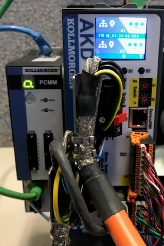
Table of Contents
- Workbench Architecture
- More Position Signals Available to the PxMM
- AKD2G Position information through EtherCAT
- Using the AKD2G capture engine
- Some Motor Feedback options require an AKD2G option
- EtherCAT (COE Init) Run up parameters
- EtherCAT Connector – on the Drive’s Top face
- Front Display
- User Units Consistency (between the IDE and Embedded Workbench)
- Safety SIL Level 3 (with AKD2G SMM option)
- I/O Action Table
- More I/O
- Safe Motion IO – AKD2G with Safety Option 2 or 3
- New project templates
- Minimum Wiring
- Stepper Motion command
- Keywords
- Fault Handling Program
- Axis Enable/Disable
- Additional Details
Workbench Architecture
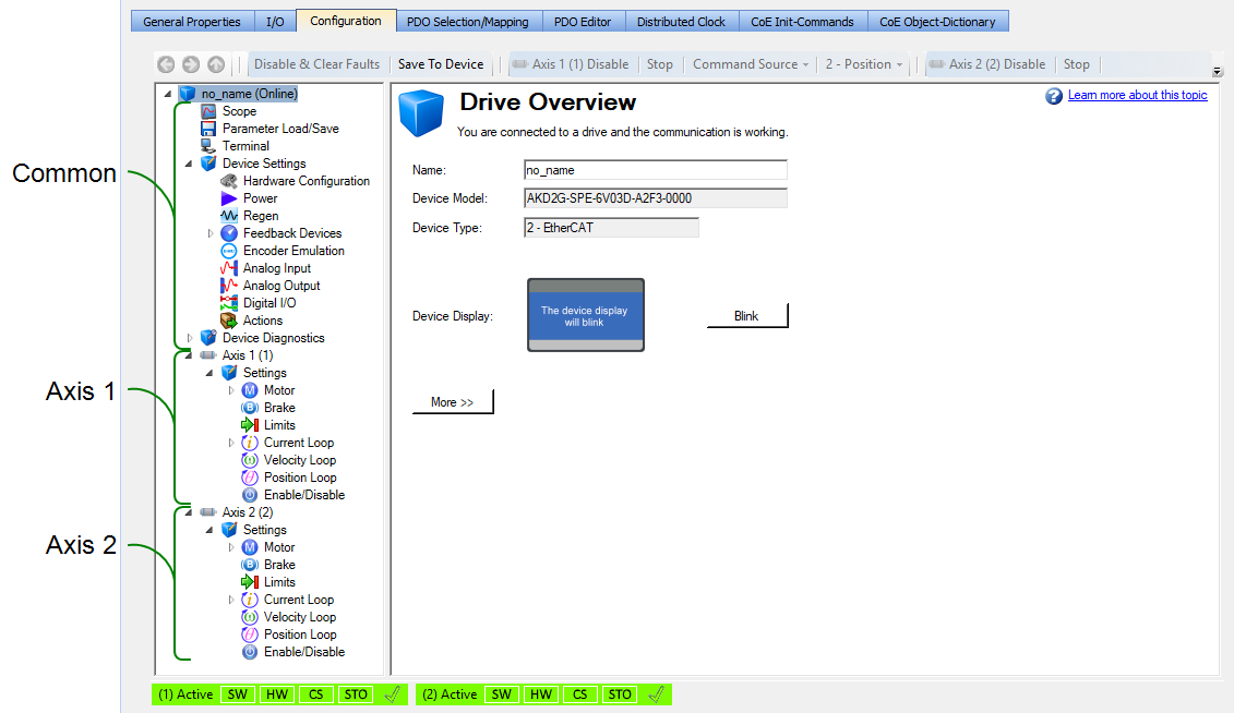
In addition to the single axis version, the AKD2G is available in a 2 axis version. For the 2 axis version, Workbench integrated into the KAS IDE (Integrated Development Environment), has items that are common to both axes then followed by a section of Axis 1 specific items, then Axis 2 specific items:
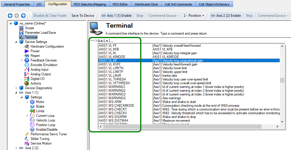
In the Workbench terminal window, which provides direct access to AKD2G parameter values in a concise format, note that many AKD2G parameter start out with an additional identifier to define the specific axis “Axis1” or “Axis2” before the <parmeter group name>. <specific parameter> it is assocated with.
Example The velocity loop proportional gain in the AKD is parameter VP.KP, in the AKD2G it is AXIS1. VP.KP or AXIS2.VP.KP
More Position Signals Available to the PxMM
AKD2G has up to 5 five independent feedbacks that can be assigned to the axis. Here is the WorkBench Screen:
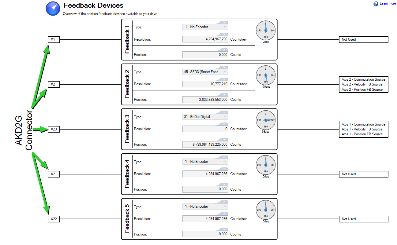
The usage of the five channels may be freely configured in the Workbench software, subject only to a few restrictions that are not physically sensible.
- Exactly one feedback channel per axis can commutate the motor.
- At most, one feedback channel per axis can serve as the command source and the same feedback channel cannot also commutate the motor.
- A feedback channel can serve as the command source for more than one axis.
- FB1 cannot commutate axis 2. FB2 cannot commutate axis 1.
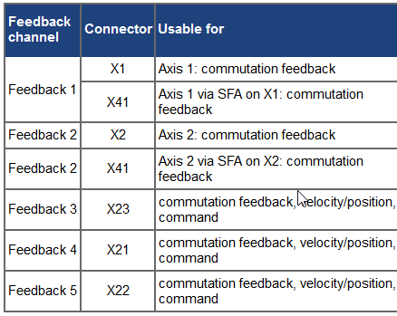
Connector X1/ Connector X2
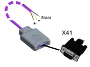
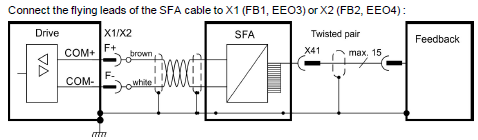
Feedback X1 and X2 only support 2 wire digital feedbacks types: SFD3 and HIPERFACE DSL. By default, each axis is assigned to feedback X1 or X2, for axis 1 and 2 respectively. To accommodate legacy feedbacks there is cable adapter SFA (P/N AKD2G-CON-SFA-000) that will plug into connector X1 or X2’s 2 wire port. On the SFA’s other side there is a 15 pole HD SubD female connector X41 that then will plug into Kollmorgen legacy feedback types (cables).
The SFA (Smart Feedback Adapter) converts conventional feedback signals to a 2-wire serial signal. SFA can be laid into the cable duct or may be mounted to a DIN rail using a standard DIN rail clip.
SFA Model numbers:
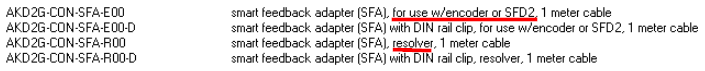
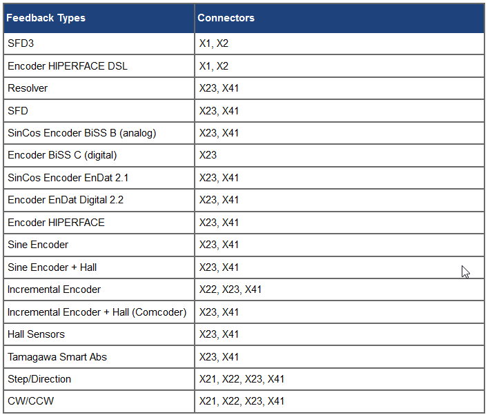
SFA supported feedback types:
| SFD | Resolver | BiSS B | EnDat 2.1 | EnDat 2.2 | HIPERFACE | Sine/Cos | Sine/Cos +Hall | Incr. Enc. | Incr. Enc. +Hall | Hall | Smart Abs | Step/Dir | CW/CCW |
Connector X23
Additionally, X23 connector is available for legacy feedbacks on feedback 3. The X23 connector provides the same d-sub 21 pin connector as AKD1 with support for the same feedbacks.
Connector X1/ Connector X2
There is also a limited support for feedbacks on the X21 and X22 connectors for feedbacks 4 and 5 that provide inputs for step and direction, A quad B incremental, and clockwise/counter-clockwise type feedback control.
Note that available connectors will depend on the drive model ordered.
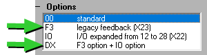
| Number of Axes | Base Model | Additional Feedbacks w/ Drive Options |
|---|---|---|
| Single Axis | (Conn X1) - SFA Adapter SFD3, DSL (Conn X21) - Step/Direction | Option F3 (Conn23) - Res, Enc, or Comcoder Option IO (Conn X22) – Step/Dir, CW/CCW or Inc Enc Option DX (Conn X22,X23) |
| Dual Axis | (Conn X1) - SFA Adapter SFD3, DSL (Conn X2) - SFA Adapter SFD3, DSL (Conn X21)- Step/Direction (Conn X22) - Step/Dir, CW/CCW or Inc Enc | Option F3 (Conn23) - Res, Enc, or Comcoder |
Note: AKD2G options allow for 2 or 3 additional feedback devices for master encoder signals and other application needs to be incorporated into the AKD2G/ KAS system.
AKD2G Position information through EtherCAT
Scaling
Feedback 1 and 2 are scaled by the following COE Parameters: 0x6091h,0x6092h,0x6096h, and 0x6097h. Some are in the KAS COE Init parameters which sets these parameters when the Ethercat Network is Initialized:
0x6092 sub Index 1 = 1048576 feed constant (shaft resolution for the feed constant) COE Init
0x6092 sub Index 2 = 1 shaft revolutions for the Feed Constant COE Init
0x6096 sub Index 1 = 60 velocity scaling (numerator) COE Init
0x6096 sub Index 2 = 65536 velocity scaling (denominator) COE Init
position value = (position internal value*feed constant)/(position encoder resolution * gear ratio)
Feedback 3,4, and 5 are scaled by the following COE Parameters: 0x60E8h, 0x60E9h, 0x60Edh and
60EEh. These can be added to the KAS COE Init parameters or using the ECATWriteSDO function blocks. Additional Feedback is possible through 60E4h.
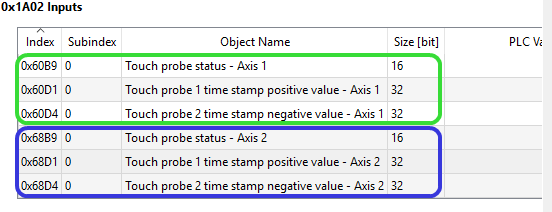
Feedback Real Time Data - Through PDO channel
The feedback data is sent back to the control through the deterministic EtherCAT PDO channel, the objects used are:
Feedback 1- 0x6064 Sub Index 0 (standard mapping)
Feedback 2- 0x6864 Sub Index 0 (standard mapping)
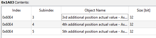
Feedback 3 - 0x60E4 Sub Index 3 (optional mapping)
Feedback 4 - 0x60E4 Sub Index 4 (optional mapping)
Feedback 5 - 0x60E4 Sub Index 5 (optional mapping)
| Standard Mapping | Optional Mapping |
|---|---|
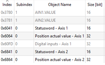 | 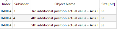 |
Using the AKD2G capture engine
Things worth noting about the high-speed capture functionality in the AKD2G:
- The AKD2G has a different set of EtherCAT Objects than the AKD. These get used when the Capture engine functionality used in MC_TouchProbe, MLAxisCfgFastIn, MLTRigSetEdge, and other KAS function blocks. The AKD2G more closely uses DS-402 standard objects for this functionality
- AKD2G has different capture engines for internal AKD2G capture setup and capture setup through EtherCAT. This means the AKD2G Workbench screen below cannot set up the AKD capture engine for use through EtherCAT.
KAS accomplished AKD2G Capture engine setup through KAS function blocks and EtherCAT COE Init commands. See the KAS help for more detail. - For both the 1 and 2 axis configurations, the AKD2G has 2 high-speed hardware inputs total on connector X21 rated for 1 usec activation/de activation delay. Note: The AKD Update rate is 2 μsec.
Some Motor Feedback options require an AKD2G option
Only HIPERFACE DSL and SFD3 feedbacks support direct single cable connections into connectors X1 and X2. All other legacy feedbacks require connector X23 or the SFA (Smart Feedback Adapter). Connector X23 is available on AKD2G options F3 and DX.
EtherCAT (COE Init) Run up parameters
For the AKD2G, the COE Init Parameters sent from the controller to the drive on Ethercat initialization have the following changes, some to line up with the DS402 standard:
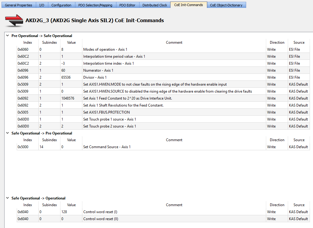
For reference here are the AKD Parameters COE Init Parameters
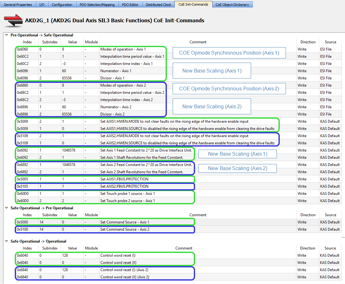
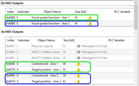
The new AKD2G COE Init Parameters are as follows (2 axis version shown):
Legend below:
The green bracket is related to Axis 1
The blue bracket is related to Axis 2
The AKD2G may contain COE Init commands for the Drive Digital Outputs:
In the AKD2G base model model some of these will not exist and must be removed from the COE init parameter list. If not, you may see the following errors when starting a project in the IDE controller log.

Single-axis drive without X22 IO option
Originally the KAS application failed to startup when the EtherCAT network contains an AKD2G single-axis drive without X22 IO option. At Ethercat init,
KAS write to AKD2G output configuration that included DOUT5.SOURCE, DOUT6.SOURCE, DOUT7.SOURCE, DOUT8.SOURCE, AOUT2.SOURCE.
If the AKD2G has no X22 IO option (e.g. AKD2G-SPE-xVxxS-A100-0000) SDO errors occur because this single axis drive model don't have all the outputs.
This prevents the Ethercat to start and reports a E33 or E31 error. Starting with version 3.07.0.87516 patch 1 the CoE init commands configure the
digital and analog outputs on X22 connector are now included only if the AKD2G model has the X22 IO option.
Note: All AKD2G dual-axis models has both X21 and X21 connectors. Whereas for AKD2G single axis, only the IO (AKD2G-SPE-xxxxx-A1IO)
and DX (AKD2G-SPE-xxxxx-A1DX) models include the X22 connector.
The WORKAROUND if using version prior to 3.07.0.87516 patch 1 is to manually remove the below entries from the "CoE Init-Commands" tab for the
AKD2G single-axis drives that didn't have the X22 IO option.
1) Set DOUT5.SOURCE - Fieldbus
2) Set DOUT6.SOURCE - Fieldbus
3) Set DOUT7.SOURCE - Fieldbus
4) Set DOUT8.SOURCE - Fieldbus
5) Set AOUT2.SOURCE - Fieldbus
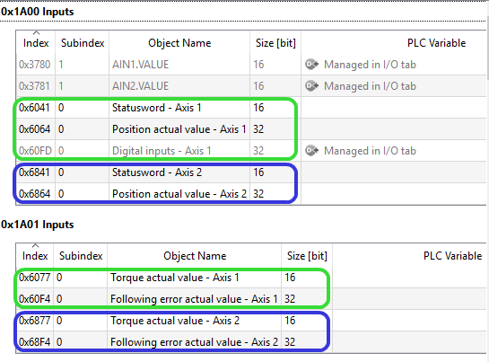
EtherCAT PDO (Process Data Object) Differences in AKD2G
PDOs are the parameters(objects) that are passed cyclically between the EtherCAT Master (PxMM) and EtherCAT Drives (AKD2G). Changes to the standard objects (from AKD) are to line up with the CoE DS402 standard specification, to add objects for a second Axis (for AKD2G dual axis models only), and add safety related objects.
The green bracket is related to Axis 1
The blue bracket is related to Axis 2
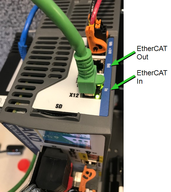
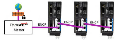
EtherCAT Connector – on the Drive’s Top face
As part of the AKD2Gs enhanced connector system the AKD2G Ethercat connection to the PxMM is on the top face. This facilitates more orderly wiring.
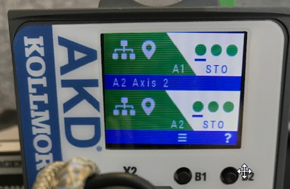
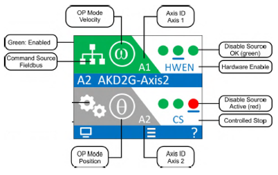
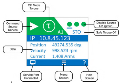
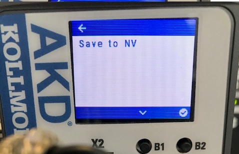
Front Display
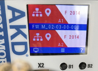
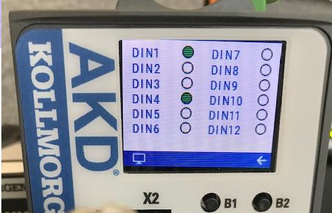
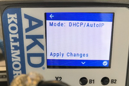
The AKD2G has more information available on the drive’s front face display. This direct information from the drive is accessible without any other software program (Workbench or the IDE)
- Status View – Displays enable status
- Status screen - when drive fault has occurred
- Display Screen Options – additional screens available through the B1/B2 buttons
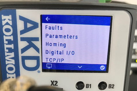
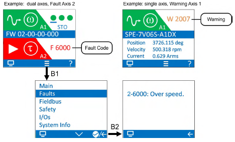
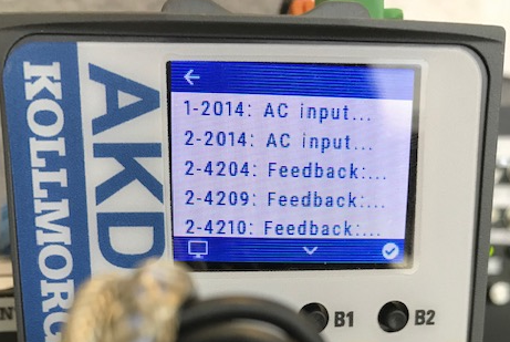
- Faults – Information on present AKD2G drive faults
- Parameters – Load or Save (Backup) to NV memory
- Digital IO Status – Present Status
- TCP/IP – Connection details
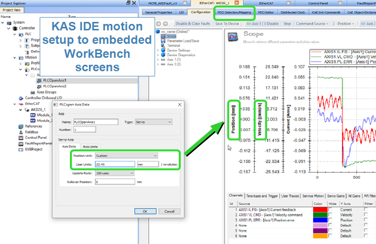
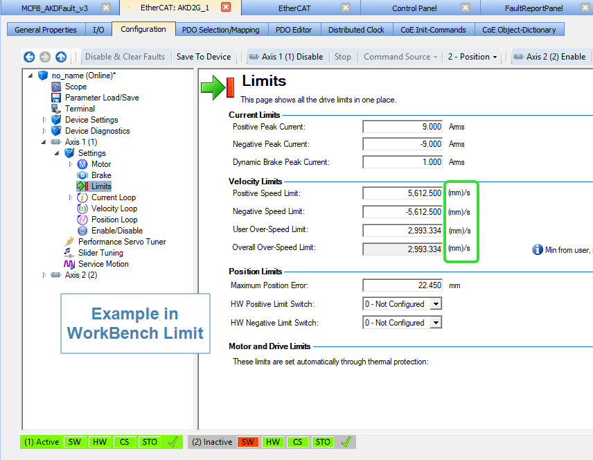
User Units Consistency (between the IDE and Embedded Workbench)
With the PxMM/AKD2G system, application units on the controller side defined in the PLCOpen Axis Data screen (with PLCopen motion)and PN Axis setup screen (with PipeNetwork motion) are now incorporated in the drive’s WorkBench screens. When a project is started up, either through the IDE or PxMM powerup, the controller side setup units are automatically transferred to the drive side. Example below shows setting up units of mm in the IDE axis setup screen carries through to the embedded WorkBench screens such as Scope and Limits:
Safety SIL Level 3 (with AKD2G SMM option)
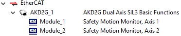
KAS version 3.03 will support the transfer of safety information from the AKD2G with SMM options #2 and #3 (available later this year) to and from a Master Safety Controller. In the PxMM, during Ethercat scan/discovery, the AKD2G default safety module profiles will be automatically added to the AKD2G device in the KAS IDE project tree.
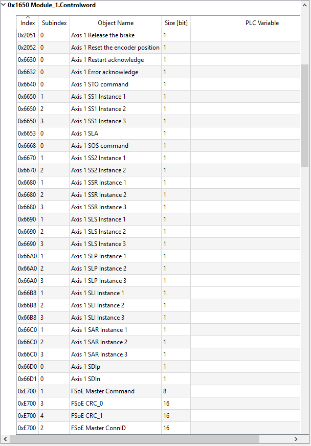
Available safety related default Ethercat PDOs are as follows:
0x1650 Basic Safety Functions (only Axis 1 shown)
In the KAS IDE project tree, an FSoE/PDO Selection tab has been added to the EtherCAT section. FSoE stands for Fail Safe over EtherCAT. This facilitates using a separate Master Safety controller to then set up and incorporates the AKD2G’s safety parameters or objects. The tab below displays: AKD2Gs safety Input (Tx) and Output (Rx) PDOs and associated safety functionality.
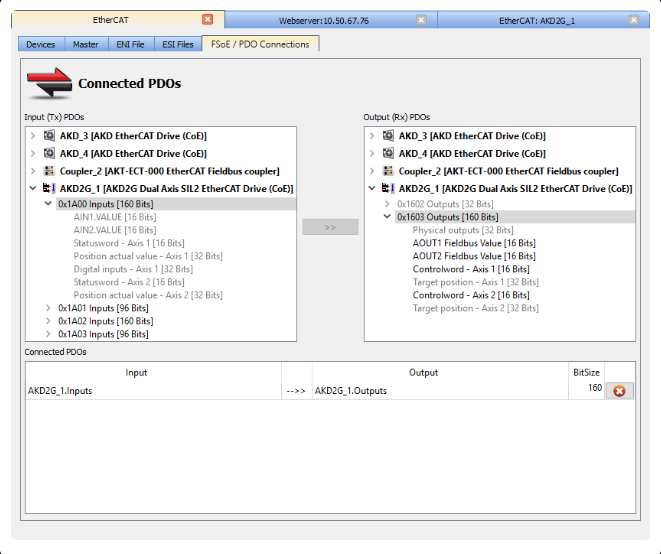
During machine operation, the PxMM runtime will copy the data between the connected PDOs. This makes it possible to transfer safety-critical process data via EtherCAT frames between the AKD2G and the Safety controller. The FSoE protocol, communication, and state machine are handled by the external EtherCAT Safety controller.
I/O Action Table
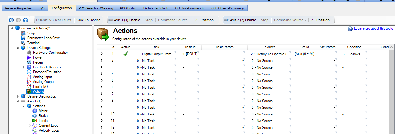
The AKD2G introduces an Action Table to configure certain tasks to run when certain events occur in the drive. Action Table replaces and extends the AKD1 digital input and output modes. This means the KAS program can use the table to configure certain actions instead of programming in the controller side. Example tasks include setting a digital output and initiating a controlled stop. Example events include detecting a level transition on a digital input comparing velocity feedback to a threshold. The AKD2G drive may be configured for up to 32 actions. Each action is defined by a set of parameters whose names identify the action (ex: ACTION#.TASK). WorkBench provides a new Actions interface screen that can be used to configure all actions on the drive.
More I/O
The AKD2G contains more I/O. This could eliminate the need for AKI remote I/O is applications with limited IO needs
Safe Motion IO – AKD2G with Safety Option 2 or 3
AKD2G Safe Motion Options #2 and #3 will be available in the second half of 2020, and include I/O point dedicated for safety connections.
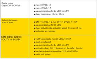
The Safe Inputs require a test pulse and the Safe Outputs generate a test pulse. Test pulses is what makes the difference between a safe I/O verses a non-safe version, gives that extra safety check to make sure the wire connection is still there.
I/O summary
New project templates
The standard IDE new project templates can be used with the AKD2G drives can be used.
Drive Warning and Fault Codes
The fault codes in the AKD are 4 digit long. Th fault codes on the AKD2G are 5 digit long and will be a different number. Example:
Bus Under Volts fault:
- In AKD it is F502
- IN AKD2G it is F2007
Also, with the AKD, warning numbers start with a nxxx. With AKD2G warning start with a Wxxxx.
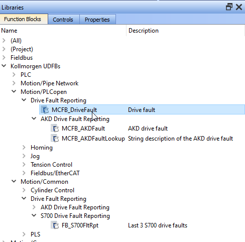
Templates in the 3.07 release of KAS IDE software were updated to use the MCFB_DriveFault function block that will report if a fault is active, and if so the number and string description of the most critical active fault. This new function works with AKD2G, AKD, S700, and AKT2G stepper drives, where previous templates had function blocks that only worked with AKD drives.
When using an AKD2G drive with a program developed in 3.06 or earlier before the MCFB_DriveFault was added, can manually add from the KAS IDE library but it requires a few steps. Can find the MCFB_DriveFault function block in the Kollmorgen UDFBs > Motion/PLCopen > Drive Fault Reporting section of the Funtion Block library shown below. In order to compile successfully, will also need to make sure the MCFB_AKDFault, MCFB_AKDFaultLookup, and FB_S700FltRpt function blocks are added to the current project as they are called inside of the MCFB_DriveFault function block.
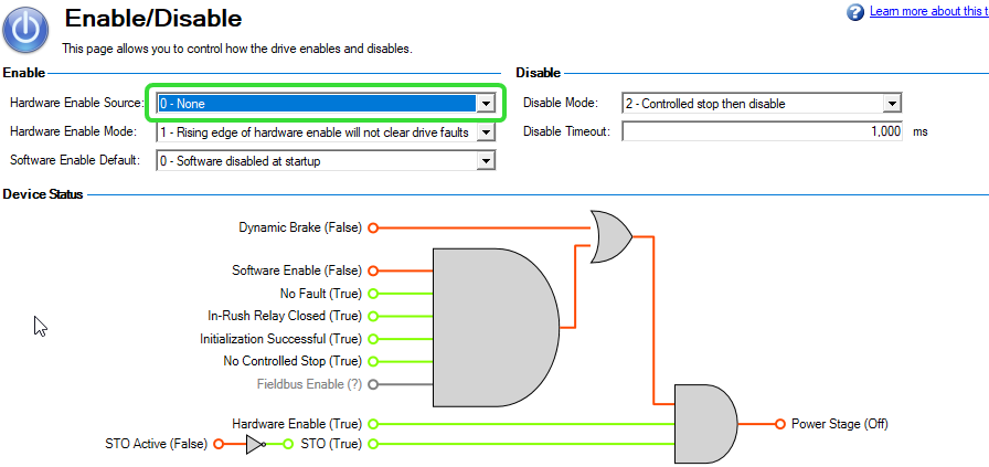
Minimum Wiring
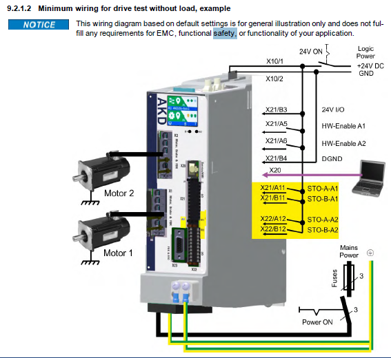
Note: For the minimal wiring that does not necessarily meet any industry standards the HW-enable signal requirement can be reset by changing the HW enable source to none:
Note: the default AKD2G disable mode is to control stop then disable instead of disable immediately. This puts the axis is control stop state that has to be cleared whenever the drive is disabled. To prevent this the Disable mode can be set to " 0 - Disable Axis immediately".
Stepper Motion command
Position Command from the PxMM through EtherCAT to the AKD2G EEO output is not yet available for the AKD2G
| Note | See KAS Stepper Control with AKT2G slices for Stepper motor control with the AKT2G remote I/O |
Keywords
To accommodate the availability of the AKD2G dual axis models, many keywords have a “AXIS1.” or “AXIS2.” suffix. Examples:
| Parameter | AKD | AKD2G |
|---|---|---|
| Position Feedback | PL.FB | AXIS#.PL.FB |
| Velocity Loop Proportional Gain | VL.KP | AXIS#.VL.KP |
| Motor Temperature | MOTOR.TEMP | AXIS#.MOTOR.TEMP |
Some that were not axis dependent have the same key word. Examples:
| Parameter | AKD | AKD2G |
|---|---|---|
| Bus Voltage | VBUS.VALUE | VBUS.VALUE |
| Drive Info | DRV.INFO | DRV.INFO |
| Save Parameters to NV memory | DRV.NVSAVE | DRV.NVSAVE |
| Regen Power | REGEN.POWER | REGEN.POWER |
Some of the DRV parameters which are axis dependent now start with “AXIS1. “ or “AXIS2“. instead of “DRV“. Examples:
| Parameter | AKD | AKD2G |
|---|---|---|
| Axis Enable | DRV.EN | AXIS#.EN |
| Axis Disable Mode | DRV.DISMODE | AXIS#.DISMODE |
Fault Handling Program
Updated Fault Handling in the KAS 2 Axis Project with PLCOpen motion engine Starter Template
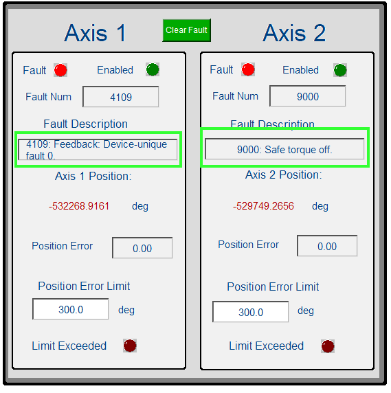
With version 3.07 IDE release , the fault monitoring (Program: FaultMonitor) for monitoring drive faults has been updated and now works all of the following drives: AKD, AKD2G, AKT2G Stepper, and S300/S700. The program FaultMonitor calls the subprogram MCFB_DriveFault which determines which drive type has a fault, then sends fault information to the fault report panel.
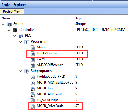
Example:
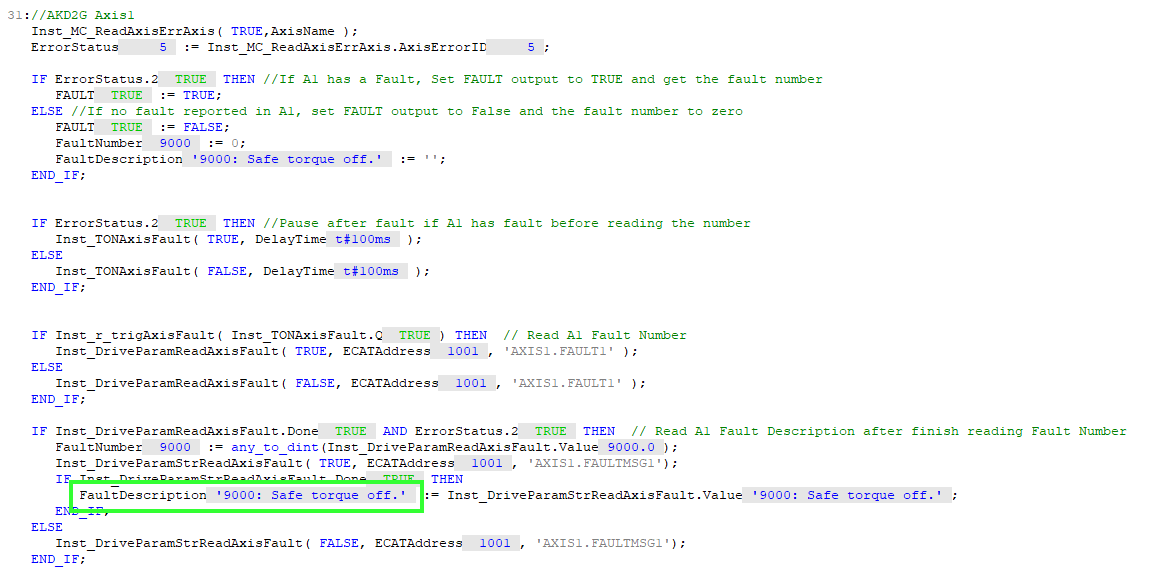
In subprogram MCFB_DriveFault there is a section of code focused on theAKD2G. Shown below is the section for Axis1. In a dual axis AKD2G the code for Axis2 directly follows in the MCFB_DriveFault subroutine (not shown).
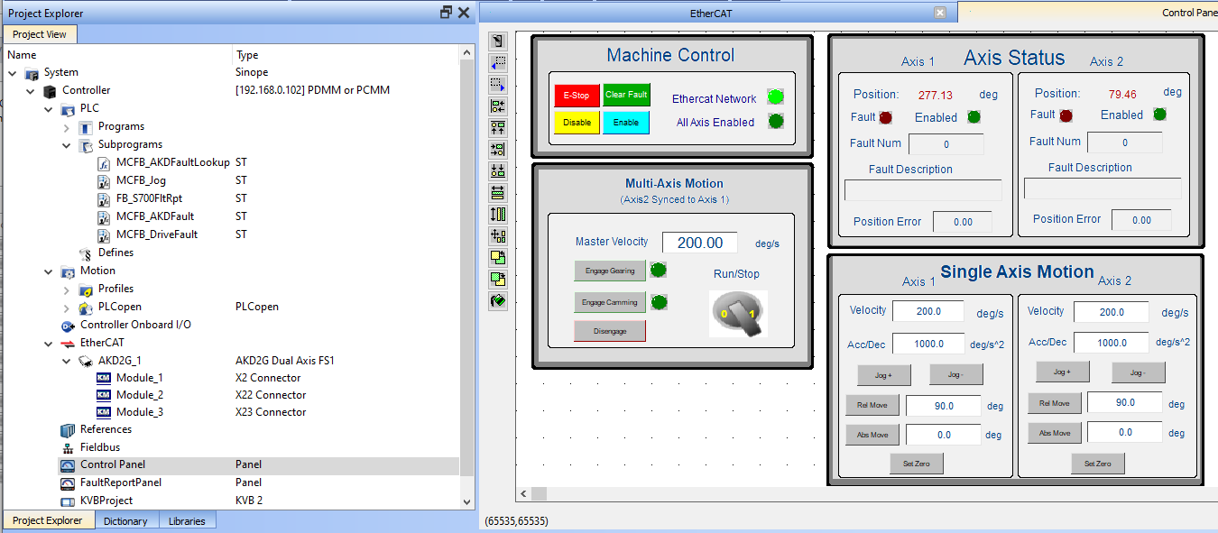
Axis Enable/Disable
With new Project templates with PLCopen motion engine the Disable mode should typically be set as follows:
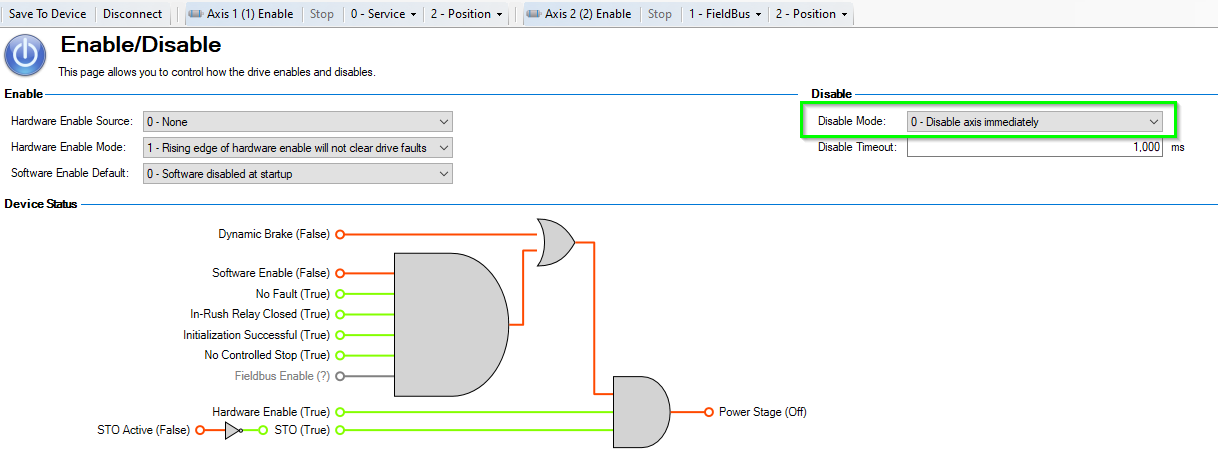
This will freely allow, from the IDE project Control panel, enabling the drive after it has been disabled.
Additional Details
In the AKD2G Online documentation, there is a section on AKD2G vs AKD:
webhelp.kollmorgen.com/kas/../AKD1vsAKD2.htm
Back to top