


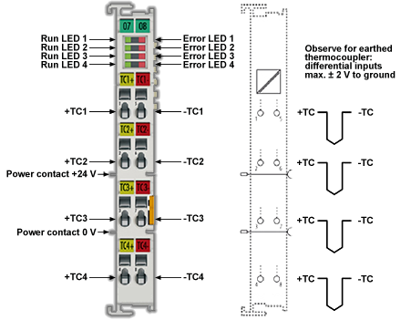
4-channel thermocouple input terminal
4-channel thermocouple input terminal, preset to type K, with wire breakage detection, 16 bit.
Specifications
| Technical Data | AKT2G-AN-400-000 |
|---|---|
| Number of inputs | 4 |
| Thermocouple sensor types | Types J, K, L, B, E, N, R, S, T, U, C (default setting type K), mV measurement |
| Input filter limit frequency | 1 kHz typ.; depending on sensor length, conversion time, sensor type |
| Connection technology | 2-wire |
| Maximum cable length to the thermocouple | 30 m |
| Measuring range, FSV | in the range defined in each case for the sensor (default setting: type K; -200 … +1370°C) Voltage: ± 30 mV (1 µV resolution) up to ± 75 mV (4 µV resolution) |
| Resolution | Internal: 16 bit Temperature representation: 0.1/0.01 °C per digit, default 0.1°C Note: 16 bit is used for FSV calculation; so, value leaps >0.01°C will occur at resolution 0.01°C depending of which thermocouple is set; e.g. type K: approx. 0.04°C |
| Supports NoCoeStorage function | yes, from firmware 01 |
| Wiring fail indication | yes |
| Conversion time | approx. 2.5 s to 20 ms, depending on configuration and fil ter setting, default: approx. 250 ms |
| Measuring error | < ±0.3 % (relative to full scale value) |
| Voltage supply for electronics | via the E-bus |
| Distributed Clocks | - |
| Current consumption via E-bus | typ. 200 mA |
| Bit width in the process data image | max. 16 byte input, max. 8 byte output |
| Max. potential ±TC against ground | 2 V, important e.g. when operating with grounded thermocouples |
| Max. differential voltage between the ±TC inputs | ±15 V permanent |
| Electrical isolation | 500 V (E-bus/field voltage) |
| Configuration | via TwinCAT System Manager |
| Weight | approx. 60 g |
| Permissible ambient temperature range during operation | -25°C ... +60°C (extended temperature range), from firmware 06 |
| Permissible ambient temperature range during storage | -40°C ... +85°C |
| Permissible relative humidity | 95%, no condensation |
| Dimensions (W x H x D) | approx. 15 mm x 100 mm x 70 mm (width aligned: 12 mm) |
| Mounting | on 35 mm mounting rail conforms to EN 60715 |
| Vibration/shock resistance | conforms to EN 60068-2-6 / EN 60068-2-27, see also installation instructions for terminals with increased mechanical load capacity |
| EMC immunity/emission | conforms to EN 61000-6-2 / EN 61000-6-4 |
| Protection class | IP20 |
| Installation position | variable |
| Approval | CE, ATEX, cULus, IECEx |
Media & Downloads
| Title | File Language | Date | Share URL |
|---|---|---|---|
| AKT2G I/O Manual EN | English | |
Share URL /sites/default/files/public_downloads/AKT2G_IO.pdf |
These files cover the standard product family line. For environmental declarations for custom products, i.e. part numbers containing “S” or “X”, visit our Environmental Compliance search.
| Title | File Language | Date | Share URL |
|---|---|---|---|
| AKT2G_SDI_safety certificate_FSM_EU_Eng | English | |
Share URL /sites/default/files/2024-09/AKT2G_SDI_safety%20certificate_FSM_EU_Eng.pdf |
| AKT2G_SDO_safety certificate_FSM_EU_Eng | English | |
Share URL /sites/default/files/2024-09/AKT2G_SDO_safety%20certificate_FSM_EU_Eng.pdf |
| Kollmorgen EU Declaration of Conformity AKT2G (DE) | English | |
Share URL /sites/default/files/public_downloads/ce_AKT2G%20IO_e.pdf |
These 3D models are intended to guide your design activities and may be used as reference information. Be sure to consult a Kollmorgen expert to ensure you have the most current and accurate information for critical aspects of design work.
| Title | File Language | Date | Share URL |
|---|---|---|---|
| AKT2G CAD Models & 2D Drawings | English | |
Share URL /sites/default/files/2025-02/AKT2G-3D-Models.zip |
Brake Chopper Terminal
Stepper Motor Terminal, 50 V DC, 5 A, Vector Control
Engineer the Exceptional
Learn how to engineer exceptional machines, robots and vehicles with the highest-performing, most reliable motors, drives, automation solutions and more.