Home >
 Knowledge Base >
 FAQs >
 Downloads >
MC_TouchProbe and Time-Based Capture
When using time-based capture with MC_TouchProbe, one may find that the accuracy of the captured position depends on the travel velocity of the captured axis.
In order to correct for timing, the application will need to set the Sensor Delay parameter (parameter 1018) using the MC_ReadParam and MC_WriteParam function blocks.
Below, is an example of the variance one may find when using time based capture. The real position of the trigger will be very close to the position reported at a slow speed. In this example, our slow speed is 1 RPM.; Then we plot the difference in reported position from the slowest speed. The difference becomes greater with increasing speed.
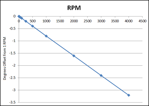
Measured at 1000us EtherCAT Cycle Rate
The table below contains the example recorded position offsets used to generate the graph above.
| RPM | Degrees Offset from 1 RPM |
|---|---|
| 1 | 0 |
| 10 | -0.0072 |
| 20 | -0.0152 |
| 50 | -0.0392 |
| 100 | -0.0792 |
| 250 | -0.1992 |
| 500 | -0.3992 |
| 1000 | -0.7992 |
| 2000 | -1.5992 |
| 3000 | -2.3992 |
| 4000 | -3.1992 |
This data can be used to calculate what the new sensor delay parameter should be. Use the following formula:

Using data from our example with an original sensor delay of 94us, we calculate:
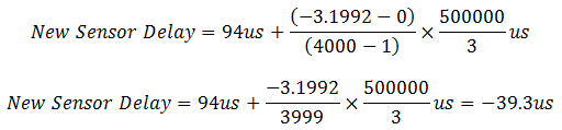
The ideal new sensor delay is -39.3us. (NOTE: Negative values are common.) Since the sensor delay parameter may only be an integer value of microseconds, we choose the closest integer value. In this case, it would be -39us.
After applying the new sensor delay, you may wish to retest to see if another small change to the sensor delay is necessary.
† The coefficient 500000/3 was calculated by converting degrees/RPM to microseconds: