


 Home >
 Knowledge Base >
 FAQs >
 Downloads >
Sensorless Control for Induction Machines (S300, S700)
Valid for S300, S700
Simple Sensorless Control for Induction Machines (Constant V/f Feed Forward Control) with S300 and S700. Parameterizing of induction machines is described on page "Operating Induction Machines S300-S700".
In all sensorless modes, the output frequency is limited to 599 Hz. If your application requires a higher output frequency, please contact our support.
Settings
| OPMODE | 0 or 1 | Velocity Mode |
| MTYPE | 3 | Induction Machine |
| FBTYPE | 10 | sensorless |
| EXTPOS | 0 | turn off additional feedback devices |
| GEARMODE | 0 |
New Commands
| MFR | rated frequency of the induction machine (in Hz) |
| MUR | rated voltage of the induction machine (in V) |
| MVR | rated speed of induction machine (in RPM) |
| MCOSPHI | power factor cosφ of the induction machine |
| VSTART | starting voltage given as a fraction of the rated voltage MUR (1=100% of MUR) |
| IQFILTK | slip compensation: weighting factor (0…2 with 1 = 100% of the rated slip) |
| IQFILTTAU | slip compensation: time constant of low pass filter (in ms) |
| SKIP1SP | skip speed 1 (in RPM) |
| SKIP1W | skip speed width 1 (in RPM) |
| SKIP2SP | skip speed 2 (in RPM) |
| SKIP2W | skip speed width 2 (in RPM) |
The V/f control scheme (Fig. 1) is a feed forward system without position or velocity feedback. For this reason, the actual velocity displayed in the DiveGUI (v_act for the oscilloscope, ASCII command “ V ”) will show a constant 0 at all times.
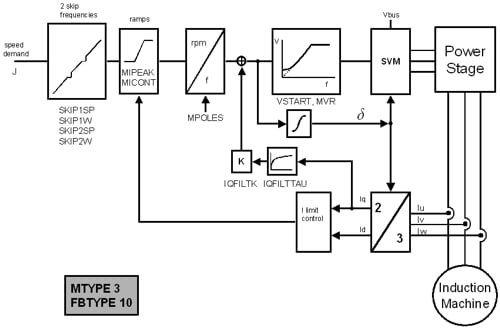
Fig. 1: Constant V/f Feed Forward Control Scheme in the S300/S700
Constant Volts per Hertz Control
|
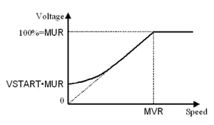
To keep the magnetic flux inside the machine at a constant level, the ratio between the applied voltage and its frequency is kept constant (Constant Volts per Hertz). MUR and MVR have to be set correctly, then the output level is automatically adjusted even to a varying supply-voltage. This will work as long as the supply-voltage is high enough to allow the induction machine to reach the commanded velocity. During standstill (f = 0) a certain minimum voltage is applied to the machine (VSTART). VSTART should be set to a value that generates a current of about 40% of the rated current at standstill (VSTART ≈ 0.1). (Fig. 2) |
Fig. 2: Actual applied voltage with respect to speed command |
Ramps
|
The ASCII commands ACC and DEC define the steepest ramps possible in the constant volts per Hertz Control. When the absolute value of the current exceeds the rated Current of the machine (MICONT) the ramps are limited to a value that falls linearly with the motor current until it reaches its peak value (MIPEAK), where the ramps are reduced to 0 (ACC and DEC = 0) . (Fig. 3 and 4) |
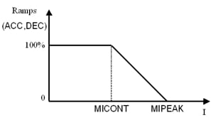 Fig. 3: Effective ramps with respect to actual current |
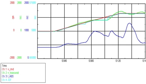
Fig4: Effect of the ramp limitation (velocity demand (red), actual value of the velocity (measured by the load machine, green), current (blue), actual value of the acceleration ramp (light blue))
Slip Compensation
The motor current can be used to compensate the slip and thus keep the motor velocity almost constant under load.
The following parameters have to be set (see Motor-nameplate):
MICONT, MPOLES, MVR, MCOSPHI, MFR
The gain factor IQFILTK is used to activate and to fine-tune the slip compensator. For IQFILTK 1 the output value of the slip compensator (ŝ) is the rated slip at rated load. IQFILTK 0 turns off the slip compensator.
Skip Speeds
To avoid certain frequencies where resonances occur and/or noise effects are more adverse, two skip speeds can be introduced to the control scheme. Defined by a speed value and a width (SKIP1SP, SKIP1W , SKIP2SP, SKIP2W , all in rpm), these skip speeds prevent the machine from running at the respective speed range for a longer time (all values in rpm).(Fig. 5)
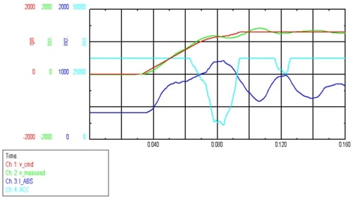
Fig. 5: Effect of the skip speeds (velocity demand (red), actual value of the velocity (measured by the load machine, green), current (blue), actual frequency (internal units, light blue))
I²t Behavior (from firmware rev. 5.36)
During sensorless operation of induction machines (V/f control) only the I²t value for the motor (MI2T) is taken into account. The behavior of the drive system is configured using the Parameters MICONT, MVR and VLIM.
As everywhere else, VLIM sets the maximum possible velocity.
When the I²t load rises above 80%, the maximum velocity is reduced (Fig. 6 left side). When MI2T reaches 100%, the maximum velocity for the motor is its nominal velocity (MVR, with MI2T 100% = MICONT this corresponds to nominal/rated Power PN of the motor). Generally a motor is capable handlig this load permanently. If the load current remains larger than MICONT and therefore MI2T rises above 100%, the permissible velocity is reduced (down to 0 at MI2T 110%).
This load-current limitation only works for loads with characteristics that are at least proportional to the velocity (e.g. friction). Most connected loads in V/f operation exhibit these characteristics. For fans or pumps the load even rises with the square of the velocity (Fig. 6 right side curve 1 and 2).
Caution ! For loads that exhibit a constant load independent of the velocity (e.g. a hanging load, Fig. 6 right side curve 3) this does not work.
The I²t load of the servo drive (DI2T) is calculated but has no effect on the velocity limit. In the case where the rated current of the connected induction machine (MICONT) is considerably higher than the rated current of the servo drive (DICONT), in an overload condition DI2T will rise to 115% and then generate a fault (F15). If it is desired to avoid this overloading of the servo drive, the limitation of the velocity can be activated by reducing the parameter MICONT to DICONT.
In the other case where the rated current of the connected induction machine (MICONT) is lower than the rated current of the servo drive, the velocity limitation described above also prevents an overload condition for the servo drive without further adjustments of the parameters.
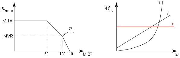
Fig. 6 Velocity limitation with respect to I²t load (left) and various load-velocity characteristics (right)
