


 Home >
 Knowledge Base >
 FAQs >
 Downloads >
RDP - Rack Drive Panel
Valid for S700
General
For a general overview of Rack Drive Panel (RDP) application see page RDP General.
Limitation
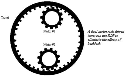
RDP works only with motors aligned to add torque. This occurs when the motors are mounted on the same side of the rack. You must ensure that the torque from the both motors are additive. If the motors are mounted in a way, that one motor is on one side of the rack and the other is on the other side, the torques would be subtractive. These kind of application cannot be controlled by the current RDP functionality on the S700.
Requirements
Rack Drive Panel functionality for two or more drives with velocity and position control is available with S700 Drives
- from Hardware Revision Number 02.10
- from Firmware Version 5.19
- with built-in Expansion Card Pos-IO-Monitor.
Control Mode
- 2 Drives: RDP applications with two drives can be controlled with velocity and position control without further equipment.
- >2 Drives: RDP applications that need more drives can be controlled in velocity mode. The position control must be done with an external controller.
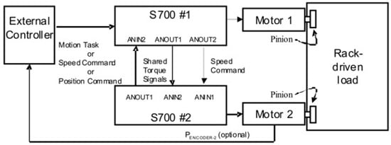
- The S700 called "Drive 1 (Master)" in the example below can be controlled by an external controller like a single standard drive. It may recive motion task commands via CANopen, Profibus or DeviceNet. It may get cyclic position or velocity commands through e.g. CANopen or EtherCat or an analog velocity command.
Variables and Commands
The following variables are used for RDP only and can be setd from the Drivegui (S700 Setup Software) terminal screen:
| RDP | Mode |
|---|---|
| 0 | RDP disabled; normal S700 operation. |
| 1 | RDP mode enabled; Enable mode = “Fault Disables Other Drive.” |
| 2 | RDP mode enabled; Enable mode = “Fault Forces Other Drive From RDP.” |
SAVE and COLDSTART are required after setting parameter RDP.
| RDPBIAS | Bias current in amps. | Normally set at 10%-25% of continuous current. |
| RDPCLAMP | Maximum output of equalization circuit in RPMs. | Normally set at 50 RPM. |
| RDPKI | Integral gain of equalization circuit. | Normally set at 13. |
| RDPKP | Proportional gain of equalization circuit. | Normally set at 300. |
| RDPON | Test variable. | Will be set to 1 only when RDP is active, otherwise 0. |
| RDPINT | Test variable. | Equals the integral value of the RDP equalization circuit. Scaled for 9000000 = 1RPM (this is 9 million = 1RPM). Limited by RDPCLAMP. |
Select Enable Mode
Select the mode of operation if one drive faults (RDP parameter). Choose either “ fault disables other drive ” or “ fault forces other drive from RDP ”. Both drives must be configured the same way.
Both drives must be configured for either “Fault disables other drive” or Fault forces other drive from RDP.” Failing to observe this may result in non-faulted drive running away at full velocity with the other drive faulted.
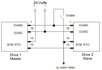
Wiring in case of "fault disables other drive" mode
The enable of the twoS700 must be wired through the BTB/RTO (Ready To Operate) contacts of both S700. This prevents one S700 from being enabled before the other is ready to be enabled.
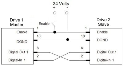
Wiring in case of "fault forces other drive from RDP" mode
The Digital Out 1 of each S700 must be wired to Digital Input 1 of the opposite S700. Output 1 is configured to show an error, O1MODE 18, and the polarity of the signal is inverted by setting DIROUT 1. A fault in a drive changes Digital Out 1 from high to low. This contact is wired to Digital Input 1. When the RDP system is configured as “Fault Forces Other Drive From RDP,” the drive will exit RDP mode when Digital Input 1 changes to low. The effect is that, when a fault occurs, it forces the opposite drive out of RDP mode.
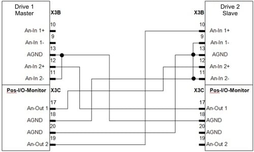
Sharing Current Signals between the Drives
The current command and velocity signals must be shared between drives.Each drive provides the current signal for the opposite drive at Analog Output 1 and reads the other drive’s current signal through Analog Input 2. Drive 2 (Slave) reads an analog velocity signal through Analog Input 1 which is provided by Analog Output 2 of Drive 1 (Master).
Configuration
Zero offsets in the analog-to-digital converter by adjusting ANZERO1 and ANZERO2
| Parameter | Drive 1 (Master) | Drive 2 (Slave) | Explanation |
|---|---|---|---|
| OPMODE | depending on application | 1 | Drive # 2 gets analog velocity command |
| ANCNFG | depending on application | 0 | |
| ANOUT1 | 0 | 0 | Analog outputs 1 used for torque sharing; will be automatically initialized |
| AN1TRIG | 100 | 100 | Sets 10V= full velocity |
| ANOUT2 | 3 | not used | velocity command from Drive 1 (Master) to Drive 2 (Slave) |
| VSCALE1 | depending on application | VLIM of Drive 1 (Master) | |
| ISCALE2 | DIPEAK of Drive 2 (Slave) | DIPEAK of Drive 1 (Master) | Scaling for torque sharing signals. This allows to use drives even with different nominal current values. |
| O1MODE | 18 (“Fault”) | 18 (“Fault”) | In case wiring option “Fault forces other drive from RDP” has been choosen. |
| DIROUT | 1 | 1 | Invert output function to get logic “high” with “no fault”. |
Tuning
With two drives
- Ensure that IN1MODE through IN4MODE are not set to 8.
- Disable the RDP variables:
RDP = 0
RDPKI = 0
RDPKP = 0
RDPCLAMP = 0
RDPBIAS = 0 - Place both drives in analog velocity mode (OPMODE=1).
- Zero the velocity loop integral gain (GVTN). Set the velocity loop proportional gain (GV) to a low initial value (< 0.1).
- Leave one drive disabled and enable the other.
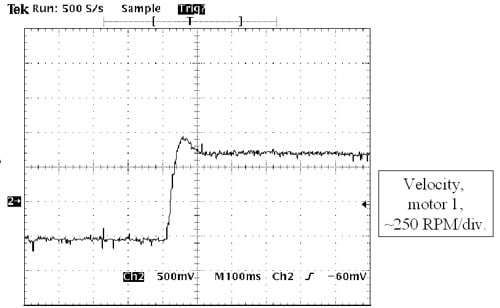
- Apply low-velocity square-wave velocity command to the drive.
- Raise the proportional gain (GV) in small steps. Keep raising the gain until the settling time in response to the step command is about 35 ms. Do not tune the system for higher gains. The fully-enabled RDP system may be difficult to stabilize. The goal of this step is to get the system operational with reasonable response. The gains can be increased after the RDP system fully enabled. (If your system does not need the velocity loop tuned this aggressively, a smaller GV would be acceptable.)
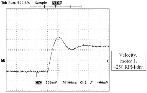
- Set the velocity loop integral gain (GVTN) to 100. Lower this gain slowly until the system overshoots by no more than 20%. You should receive a response like this:
(If your system does not need the velocity loop tuned this aggressively, a larger GVTN would be acceptable.) - Half the proportional gain (GV). The gain of the servo loop naturally doubles when you enable the other drive. This is because once the drive is enabled it takes half the load, making the system appear only about half as difficult to move. This effectively doubles the servo gain. When the proportional gain is cut in half, the system slows down and overshoots more
- Disable the first drive.
- Enable the second drive and repeat the tuning process. The resultant gains should be same for both drives.
- Disable the second drive. Leave the first drive disabled.
- Configure both drives for RDP. Recall the Enable Mode you selected above (refer to “Selecting Enable Mode” section above). If you selected “Fault Disables Other Drive,” type “RDP = 1” in both drives. If you selected “Fault Forces Other Drive From RDP,” type “RDP = 2” in both drives. You must configure both drives for the same Enable Mode. You must wire the enable inputs appropriately for the selected mode as discussed in “Wiring the Enable.”
- Configure the equalization loop prefereably in the second drive (but not both) setting the variables RDPCLAMP, RDPKI, and RDPKP. Normal values are
RDPCLAMP = 50
RDPKI = 13 and
RDPKP = 300. - These values rarely change. However, if you need to increase the rate at which the loops equalize, raise RDPKI and RDPKP in increments of 20% until desired performance is attained. RDPCLAMP limits the maximum output of the equalization circuit to 50 RPM. This is normally adequate to deal with errors that occur in velocity command and feedback.
Stand clear of the machine. Be prepared to remove power quickly in case the system becomes unstable. Provide mechanical guards to protect people and equipment if the system becomes unstable. When drives are switched to RDP mode, the system may become unstable, even if it was completely stable when one drive was operated at a time.
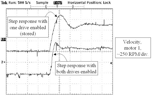
- Enable both drives. Ensure that the system is stable by subjecting the rack to step changes in velocity. Be prepared for the system to become unstable when the second drive is enabled.
- Observe the step response of one motor or the other. The step response should change from the top waveform when one drive is enabled to the bottom waveform when both are enabled.
- Set the bias current according to the application with the variable ±RDPBIAS. This is typically set to between 10% and 25% of drive continuous current. Larger levels of bias current keep the rack in tension or compression with larger loads, but also use more power and generate more heat. They also reduce the peak torque output of the servo system. Set RDPBIAS positive in one drive and negative in the other.
- If faster servo performance is required, raise the proportional gain (GV) and the integral gain (GVTN) on both drives in 10% increments. Raising the servo loops gains can cause instability in the RDP equalization circuit that is manifested by high-frequency, sustained oscillations.
With more than two drives
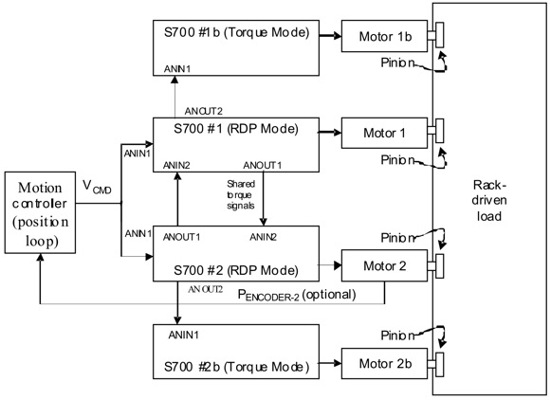
If more than two drives are required to provide sufficient torque for an application torque mode drives can be added in pairs. This is possible only in case the external controller is doing the position control and sending analog velocity command to two drives in parallel. The second analog output of RDP Drive 1 (Master) will be used for the torque command to the first torque drive instead of sending a velocity command to the second drive. The RDP Drive 2 (Slave) will send a torque command to the second torque drive. Note that the RDP-mode drives must be manually configured to produce current command on AOUT2.
The tuning process must be modified when using more than two drives. First tune the system with just the two RDP-mode drives as discussed above. After that, each time a pair of torque mode drives is added, it increases the torque applied to the system, effectively increasing the loop gain. Thus, GV must be reduced in proportion to the total number of drives that are enabled. For example, if the tuning process above produced a value of GV=1 when just the RDP drives were connected, expect to reduce this value to GV=0.5 if two torque-mode drives were added. Similarly, expect to reduce the value to GV = 0.33 if four torque-mode drives were added. In general, expect the product of GV and the number of enabled drives to remain approximately constant.
Stand clear of the machine. Be prepared to remove power quickly in case the system becomes unstable. Provide mechanical guards to protect people and equipment if the system becomes unstable. When drives are switched to RDP mode, the system may become unstable, even if it was completely stable when one drive was operated at a time.
Back to top