


 Home >
 Knowledge Base >
 FAQs >
 Downloads >
EMC
Table of Contents
What is EMC
The abbreviation EMC stands for Electro Magnetic Compatibility, and is the ability of an item of equipment to operate satisfactorily in the electromagnetic environment, without itself causing electromagnetic interference that would be unacceptable for other equipment .
Devices that produce interference can be categorized to four main categories:
- Mains fluctuation with industrial mains (countermeasure: magnetic stabilizer)
- Harmonics interference in frequency range 100 Hz ... 2 kHz (countermeasure: selective harmonic filter)
- Transient interference signals in frequency range up to 300 MHz (countermeasure: low pass filter)
- Sine interference signal in frequency range up to 1 GHz (countermeasure: broad band low pass filter)
Usually categories 3 and 4 can be found. Such interference may have influence on electronic circuit functionality or may destroy them.
The EMC law EMVG is intended to regulate those technical characteristics of electrical or electronic products that could cause electromagnetic interference (RFI generation) or that could be affected in their operation by electromagnetic interference (susceptibility to interference).
Standards and regulations
This section presents and explains the legal regulations and standards that are required at present for servo amplifiers to fulfil the EMC directives.
EC Directive: EC EMC Directive 2004-108
Used standard for servo amplifiers : EN 61800-3 Product standard
See Standards and Directives for other standards and directives.
EMC Requirements
There are many test and measurement regulations that apply to EMC. It must be noted, that Kollmorgen Servo Amplifiers are intended exclusively for use in industrial areas. Basically, all EMC requirements in the form of test and measurement regulations can be divided into two main groups:
Interference immunity (noise immunity)
is the minimum immunity that is required of the equipment against the effects of electromagnetic interference that can be coupled into the connecting cables or the equipment housing electrically, (i.e. as a voltage) inductively or capacitively.
Interference emission (RFI generation)
is the maximum permissible level of interference that the equipment may produce. The interference emission mainly influences the environment directly through the connected cables, as interference signals (electrical, inductive or capacitive), through radiation from the housing or internal components, or by radiation from the attached cables.
Area of application
Class A (application in industrial area) and Class B (application in residential and commercial areas) are defined within the area of application "first environment"
Industral areas
The Class A (industrial areas) includes all sites that are not intended to be connected to the normal public utility (low voltage) electrical supply. It is assumed that the equipment will be connected to a supply network with its own high/medium voltage power distribution transformer.
Residential areas
The Class B (residential and commercial areas) includes all sites that do not have their own substation transformer, as described under Class A (i.e. small companies, residential buildings, commercial and mixed operations).
Test requirements
Interference immunity
The variety and variation of the equipment in the application areas covered by the standards makes it impossible to define precise criteria for evaluating the results of the interference immunity tests. Three evaluation criteria are used as a basis for the assessment and evaluation of the response to interference during the interference immunity tests.
Criterion A
The equipment must continue to operate as specified. There must be no impairment of the operational behavior or loss of functionality that takes the equipment below a minimum quality of operation that is defined by the manufacturer, as long as the equipment is operated according to the specification. In certain cases, the minimum quality of operation may be replaced by a permissible reduction in the quality of operation. If the minimum quality of operation or permissible reduction in the quality of operation is not defined by the manufacturer, then these values may be derived from the product description as well as from the expectations that the user may reasonably have of the equipment in specified operation.
Criterion B
After the tests, the equipment must continue to operate as intended. There must be no impairment of the operational behavior or loss of functionality that takes the equipment below a minimum quality of operation that is defined by the manufacturer, as long as the equipment is operated according to the specification. In certain cases, the minimum quality of operation may be replaced by a permissible reduction in the quality of operation. An impairment of the operating behavior is permitted during the test. However, an alteration of the operating mode that was set or a loss of stored data is not permitted. If the minimum quality of operation or permissible reduction in the quality of operation is not defined by the manufacturer, then these values may be derived from the product description as well as from the expectations that the user may reasonably have of the equipment in specified operation.
Criterion C
A temporary loss of function is permitted, provided that the function restores itself, or can be restored by using the adjustment or operating controls (reset function).
Interference emission
The interference that is emitted by the equipment is measured (r.m.s. and average values). Limit values are defined for the interference emission in various frequency bands. These limits must not be exceeded.
EMC measures for digital servo amplifiers
A clear separation of EMC measures into two areas:
- Improving the interference immunity, and
- Reducing the interference emission
is only partially possible, since there is a strong interaction between the measures for interference emission and those for interference immunity. The interference immunity of complete systems depends mainly on the quality of the interference immunity of the individual components and systems that are used. The interference emission is very dependent on the wiring, configuration and installation requirements, as well as the installation site. The following is a summary of the most important EMC recommendations.
The EMC measures that we recommend have been investigated in the test laboratory, and ensure that the digital servo amplifiers, together with the peripheral equipment that is described, will fulfil the relevant EMC standards.
Shielding
The cables listed below must be shielded.
| Resolver cable | Connect the shield to the connectors at both ends |
|---|---|
| Motor cable | Connect the shield to the connector or cable screw gland on the motor, and to ground at the amplifier end |
| Holding Brake Cable | Connect the shield to the connector or cable screw gland on the motor, to ground at the amplifier end |
| Brake cable | Connect the shield to the cable screw gland on the external brake resistor, to ground at the amplifier end |
| Supply power cable | For servo amplifiers without a built-in mains filters: Connect the shield to the PE terminal on the mains filters, to ground at the amplifier end. For servo amplifiers with a built-in mains filters : no shield required |
| 24V cable | For servo amplifiers without a built-in supply line filter: Connect the shield to the PE terminal on the mains filters, to ground at the amplifier end. For servo amplifiers with a built-in mains filters : no shield required |
| Analog signals | Connect the shield to the analog reference ground at the PLC, to ground at the amplifier end |
| Position output | Connect the shield to the connector on the amplifier, to GND on the CNC |
| Fieldbus cable | Connect the shield to the connector on the amplifier, to GND on the CNC |
- Terminal clamps must be installed as close to the equipment as possible.
- Make a wide-area grounding (earth) of the shield at both ends.
- The shield braid should provide at least 85% coverage.
- Ground any unused cores of the motor cable to the PE at both ends.
- Route all control, bus and signal cables with at least 20 cm separation from the shielded motor cable.
- Route all the cables inside the switchgear cabinet as close as possible to the reference ground - cables in free air act simultaneously as transmitting and receiving antennae.
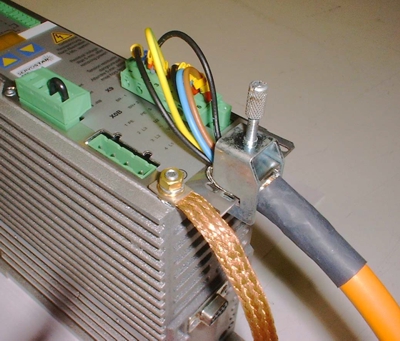
- Because of the motor and shield capacitance to ground, high peak currents flow in the shield of the motor cable (approx. I(t)=20A/µs or more, depending on the type of controller). In order to contain and ground these peak currents, it is very important that the shield has a low impedance (large area) connection to the reference ground for EMC (mounting plate) at both ends.
- Depending on the application, it may be advisable to provide another low impedance path between the motor and the servo amplifier.
- If unfiltered RFI fields can emerge from the equipment and be picked up by the attached cables, then these cables will themselves function as antennae and radiate the interference into free space.
Note: For more information on the various methods and combinations of methods for grounding and shielding, see the application note EMI Checklist
EMC ground
- Make all connections to the EMC ground as short as possible, with large area connections.
- Take care that all metallic housings have a good contact to the galvanized mounting plate. Exception: Supply line choke (see below)
- Make a large-area, electrically conductive connection between all metallic components (equipment housing of the servo amplifier, filter housing, motor housing, shield braid of the cables) and a star point (mounting plate).
- Avoid using coated surfaces such as Eloxal or yellow-chroming (rails, screws). These can have very high frequency-dependent impedance (skin effect). A galvanized mounting plate is very suitable as an EMC ground, used as a star point (to avoid wiring loops). It provides an ideal large-area low-impedance connection to the equipment that is mounted on it and to the shields that are connected. The interference energy is thus effectively grounded.
- Take care that all electronic or electrical components that could be a source of HF fields are within a closed metal casing (Faraday cage).
Note: For more information on the various methods and combinations of methods for grounding and shielding, see the application note EMI Checklist
Protective earth (PE)
PE connections as per EN 60204 are dimensioned purely for the protection against contact voltage and dangerous body currents. Because of the high cable impedance, it is impossible for the PE system to provide adequate grounding for RFI fields. The PE system cannot be considered to be equivalent to the EMC ground, although they are joined directly together. The EMC ground has the task of providing a low-impedance grounding of HF interference signals.
- Provide an additional connection for all metallic housings to the PE rail in the switchgear cabinet (protection against contact).
- Connect the servo amplifier to the EMC ground by a short connection with a large surface area (braided band) to ensure low lead inductance.
- Wire the PE connection for the individual system components in a star connection to the potential equalization rail. In this way, you can avoid creating PE connection loops that could function as antennae and pick up interference.
- Unfavorable PE connections or wiring loops can bypass the EMC measures, and make them ineffective.
Motor choke for digital servo amplifiers
The motor choke is designed as a current-compensated choke, which means that the 3 coils are wound symmetrically on one core.
The high switching frequencies and fast switching edges in digital servo amplifiers produce capacitive currents between the three phases (U,V,W) and the shield. These currents then flow to ground through the shield. The result is that peak currents up to 20A/µs can be generated in the shield, depending on the cable length and capacity (which depends on the cable type). These shield currents load both the servo amplifier and the motor, and in large system they can lead to voltage offsets that may interfere with other components.
- All cables between motor chokes, motor and servo amplifier must be shielded
- The motor chokes should be mounted as close as possible to the servo amplifier.
- Select the smallest possible wire cross section (observe the current carrying capacity) to get the highest possible wire resistance
Mains Filters
All cables between the mains filters and the servo amplifier must be shielded. Mains filters are required for all amplifiers that do not have a built-in filter: S640/670 and AKD-****06.
- Always take care that the filter housing has a wide-area connection to the EMC ground (mounting plate).
- The filter should be mounted as close as possible to the servo amplifier.
- It is possible to use one common mains filters for several servo amplifier which are connected in parallel.
Mains Chokes
Mains chokes are only required for S640/670, to improve the power factor and protect the B6 bridge rectifier. With S748-S772 a mains choke may be required as well, if the mains power supply is more than 3% asymmetric.
- The mains choke must have an insulated fixing on the mounting plate, the connection to the EMC ground must have a high impedance.
- But you must still make a connection to the protective earth (PE), to ensure contact safety.
