


1-Channel Incremental Encoder Interface
This terminal is an interface with 24 V inputs for the direct connection of incremental encoders. A 32 bit counter with a quadrature decoder and a 32 bit latch for the zero pulse can be read, set or enabled. The measurement of period and frequency is possible. The gate input allows the locking of the counter, selectively with a high or low level. The latch input is similarly configurable and evaluates high or low levels. The AKT2G-ENC-180 supports distributed clocks, i.e. the input data can be synchronously acquired with other data that are similarly connected, distributed to distributed clock terminals. The universal system accuracy is around < 100 ns. With a moving axis, the micro-increment functionality offers 256 times higher axis position resolution than physically provided by the encoder. The AKT2G-ENC-180 can also be used as a single-channel 32/16 bit counter on channel A, in which case the signal level on channel B defines the count direction.
Specifications
Please refer to the KAS webhelp for important information regarding the application and use of safety rated I/O terminals.
| Technical Data | AKT2G-ENC-180-000 |
|---|---|
| Sensor Inputs | 1 |
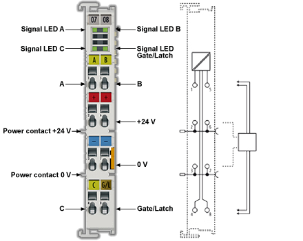
| Encoder connection | A, B, C, gate/latch input, 24 V |
| Encoder operating voltage | 24 V |
| Signal voltage "0" (inputs A, B, C, gate/latch) | 0 V .. 5 V (EN 61131-2, type 1) |
| Signal voltage "1" (inputs A, B, C, gate/latch) | 15 V .. 30 V (EN 61131-2, type 1) |
| Counter | 1 x 32/16-bit binary, switchable |
| Limit frequency | max. 400,000 increments/s with 4-fold evaluation), corresponds to 100 kHz |
| Quadrature decoder | 4-fold evaluation |
| Timestamp resolution | 1 ns |
| Timestamp accuracy | 100 ns |
| Commands | Read, set, latch, gate function |
| Power supply for electronic | via the E-Bus |
| Distributed Clocks | yes |
| Supply voltage | 24 VDC (-15 %/+20 %) |
| Current consumption from the E-bus | typ. 130 mA |
| Current consumption from the power contacts | 0.1 A (excluding sensor load current) |
| Electrical isolation | 500 V (E-bus/field voltage) |
| Supports NoCoeStorage function | yes |
| Weight | approx. 50 g |
| Permissible ambient temperature range during operation | -25 °C ... +60 °C (extended temperature range) |
| Permissible ambient temperature range during storage | -40 °C ... +85 °C |
| Permissible relative humidity | 95%, no condensation |
| Dimensions (W x H x D) | approx. 15 mm x 100 mm x 70 mm (width aligned: 12 mm) |
| Mounting | on 35 mm mounting rail conforms to EN 60715 |
| Vibration/shock resistance | according to EN 60068-2-6/EN 60068-2-27, see also Installation instructions for terminals with increased mechanical load capacity |
| EMC immunity/emission | conforms to EN 61000-6-2 / EN 61000-6-4 |
| Protection class | IP20 |
| Installation position | variable |
| Approval | CE, ATEX, cULus |
Media & Downloads
| Title | File Language | Date | Share URL |
|---|---|---|---|
| AKT2G I/O Manual EN | English | |
Share URL /sites/default/files/public_downloads/AKT2G_IO.pdf |
These files cover the standard product family line. For environmental declarations for custom products, i.e. part numbers containing “S” or “X”, visit our Environmental Compliance search.
| Title | File Language | Date | Share URL |
|---|---|---|---|
| AKT2G_SDI_safety certificate_FSM_EU_Eng | English | |
Share URL /sites/default/files/2024-09/AKT2G_SDI_safety%20certificate_FSM_EU_Eng.pdf |
| AKT2G_SDO_safety certificate_FSM_EU_Eng | English | |
Share URL /sites/default/files/2024-09/AKT2G_SDO_safety%20certificate_FSM_EU_Eng.pdf |
| Kollmorgen EU Declaration of Conformity AKT2G (DE) | English | |
Share URL /sites/default/files/public_downloads/ce_AKT2G%20IO_e.pdf |
These 3D models are intended to guide your design activities and may be used as reference information. Be sure to consult a Kollmorgen expert to ensure you have the most current and accurate information for critical aspects of design work.
| Title | File Language | Date | Share URL |
|---|---|---|---|
| AKT2G CAD Models & 2D Drawings | English | |
Share URL /sites/default/files/2025-02/AKT2G-3D-Models.zip |
Brake Chopper Terminal
Stepper Motor Terminal, 50 V DC, 5 A, Vector Control
Engineer the Exceptional
Learn how to engineer exceptional machines, robots and vehicles with the highest-performing, most reliable motors, drives, automation solutions and more.