Home >
 Knowledge Base >
 FAQs >
 Downloads >
Coupler Sizing - AKT2G Remote IO
Introduction
The AKD-PDMM controller/drive, PCMM standalone controller, AKD, AKD2G, and S700 drives all contain hardware I/O that can be used in an application to interface to other control elements on the machine. Typically, to minimize overall system cost, IO point on these products are used first before the AKT2G Remote I/O is incorporated. AKT2G Remote I/O will also be used if a signal type not supported by these products is needed in the application (Example: Thermocouple Module). This lesson reviews how to put together a remote AKT2G Remote I/O Block.
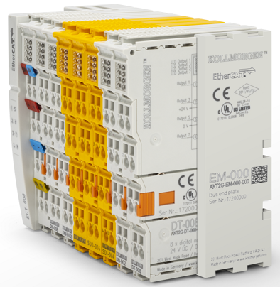
Required Parts to a AKT2G I/O Block
Every AKT2G I/O block must consist of the following:
- 1 EtherCAT coupler: AKT2G-ECT-000-000
- 1 or more Modules (slices)
- 1 End Module: AKT2G-EM-000-000
The AKT2G family
Consist of the following slices:
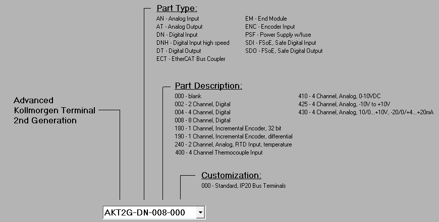
Complete model number list:
|
Part Number |
Description |
|---|---|
|
AKT2G-ECT-000-000 |
EtherCAT Coupler for AKT2G modules (slices) |
|
AKT2G-DN-008-000 |
8-channel digital input terminal 24 V DC, filter 3.0 ms, 1-wire system |
|
AKT2G-DNH-008-000 |
8-channel digital input terminal 24 V DC, filter 10 µs, 1-wire system |
|
AKT2G-DN-002-000 |
Up/down counter 24 V DC, 100 kHz, 32 bit counter depth |
|
AKT2G-DT-008-000 |
8-channel digital output terminal 24 V DC, 0.5 A, 1-wire system |
|
AKT2G-AN-430-000 |
4-channel analog input, -10/0…+10 V, -20/0/+4…+20 mA, 16 bit |
|
AKT2G-AN-240-000 |
2-channel input terminal PT100 (RTD) for resistance sensors, 16 bit, 2-, 3-wire system |
|
AKT2G-AN-400-000 |
4-channel thermocouple input terminal, preset to type K, with wire breakage detection, 16 bit |
|
AKT2G-AT-410-000 |
4-channel analog output terminal 0…10 V, 12 bit, 1-wire system |
|
AKT2G-AT-425-000 |
4-channel analog output terminal -10 V…+10 V, 12 bit, 4 x 2-wire system |
|
AKT2G-ENC-190-000 |
Incremental encoder interface with differential input, 16/32 bit |
|
AKT2G-ENC-180-000 |
1-channel incremental encoder interface, 32 bit |
|
AKT2G-SM-L50-000 |
Stepper motor terminal with incremental encoder, 50 V DC, 5 A (Imax), 2 phases 2 digital inputs 24 V DC 4 digital inputs for an incremental encoder vector control |
|
AKT2G-SDI-004-000 |
4-channel digital input terminal, Safety, 24 V DC |
|
AKT2G-SDO-004-000 |
4-channel digital output terminal, Safety, 24 V DC, 0.5 A |
|
AKT2G-EM-000-000 |
Bus end cover for E-bus contacts |
|
AKT2G-PSF-024-000 |
Power supply terminal with fuse, 24 V DC |
I/O Block Sizing
In the AKT2G Remote I/O system, many modules can be connected to one ECT2G coupler. In most applications, one Remote I/O block is all that is needed. The following are guidelines to determine how many AKT2G-ECT-000-000 EtherCAT Coupler modules will be required.
Each remote IO configuration (block) starting with an AKT2G-ECT-000-000 coupler must not exceed any of the following limits:
- Slice Quantity Limitations The max number of slices connected to the coupler is 64
- Data Bus Limitations The max number of data bytes the coupler can process to and from the EtherCAT network is 1024 bytes of input and 1024 bytes of output. The number of bytes a slice has is defined in the row "Bit width in the process image" in the specification sheet for each slice
- Power Limitations Each bus coupler module can provide:
- Internal Bus (5 volt logic) power - 2 Amps (2,000 mAmp)
- 24V output power - 10 Amps (10,000 mAmp)
A Power Feed Module AKT2G-PS-024-000 can be added for an additional 10 Amps of 24V output power.
More
Other guidelines when putting together a AKT2G remote I/O block
- An AKT2G-EM-000-000 End Module provides protection for side plane logic contacts on last slice in the I/O block
- 24 Volt power module – AKT2G-PSF-024-000 will provides a gateway to bring in additional 24 VDC power to the modules mounted to the right. It is not connected to the 24vdc power in the slice to the left
- For high-speed inputs, the AKT2G-DNH-008-000 Digital Input Modules offer very fast response but have less signal filtering (of high-frequency spikes).
Attached is a calculation spreadsheet to help determine how many AKT2G- ECT-000-000 couplers are needed in an application.