


 Home >
 Knowledge Base >
 FAQs >
 Downloads >
Sine Encoder
General
Sine Encoders are sensors for the measurement of position changes (linear or rotary), which can measure both distance and direction. These sensors are used as feedback systems e.g. in servo drives. Sine encoders do not determine an absolute position.
Sensors for determining unique angle and positions are absolute encoders.
Sine and Cosine Channels
Sine Encoders are very similar to incremental encoders so it's helpful if the incremental encoder information is reviewed prior to this page. The difference between incremental encoders and sine encoders is simply that the A and B data channels are sent to the controller as 1 volt peak-to-peak sinewaves instead of the digital pulse format. Common output signal levels are TTL, HTL (both digital signals), as well as 1 Vss and 11 µA (analog signals).
Reference pulse
Disadvantage: after a blackout the absolute position is no longer known. Therefore at positioning systems so-called reference motion tasks to an independent position sensor are executed after switching on. Some rotary encoders distribute a reference impulse (index, zero pulse) per one full turn on a third channel. An external reference sensor can be dropped in this case.
Function
Sine encoder can work photoelectrically or magnetically.
Photoelectrical scanning
A light beam is leaded through a condenser, through an scanner plate with lines and through an apperture to a photo sensor element (usually a phototransistor).
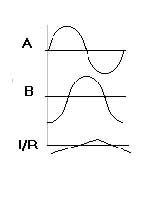
A plate with slits is located between the light-emitting diode and two optical sensors arranged with a small offset. If the plate rotates, the light beam is modulated cyclically between LED and sensors. The two sensors deliver two 90° phase shifted, symmetrical, sine similar signals. If the plate moves to the right, the sine signal of the first channel is leading opposite the second channel by 90°. In the opposite direction, the sine signal of the first channel is lagging opposite the second channel by 90°.
Magnetic scanning
The measuring scale of an increment measuring system with a magnetic scanning is made of a magnetically hard strap in which a dividing by magnetization has been impressed. The scanner plate carries e.g. four Hall Sensors which are wired similar to the optical multi area scanning . The partition period can be at these systems up to 5 mm. The magnetic scanning is used if the measuring system cannot get encapsulated with tolerable effort. It can be produced insensitively against liquids and dirt.
Signal evaluation
The servo amplifier evaluates the impulse number, impulse frequency and phase relationship and calculates the distance, speed and direction from these information. Due to the sine form of the signals an internal interpolation of the position can be done, which permits another rise of the precision.
If the rotary encoder is used in a servomotor, it usually has additional tracks. These usually represent tracks for commutation signals. They can be analog made of sine/cosine signals shifted by 90° (so-called C/D track or Z1 track) or made of pitch circles at the block commutation.
Application Notes
- Resolution processing of Sine Cosine Encoders
- Supervision of Sine Cosine Encoders
- Sporadic error message F04 with linear measuring systems
