


 Home >
 Knowledge Base >
 FAQs >
 Downloads >
RDP General
Valid for S700 / S300
For configuration of RDP functionality see RDP - Rack Drive panel
Overview
Rack-drive loads place special requirements on the servo control system. On one hand, rack-and-pinion mechanisms have a relatively large amount of lost mechanical motion or backlash. Many applications require that the rack be driven by two motors that place the rack in tension or compression to remove this backlash, at least while the mechanism is under light loads. This demands that the velocity loops within the drives operate, to a large extent, independently. On the other hand, the two drive systems are strongly linked through the rack. When the backlash is taken up, the average speed is the same for the two motors. This linkage prevents using fully-independent, integrating velocity loops for the two drives. The special needs of rack-driven loads force system designers to use control schemes developed specially for the mechanism. This document outlines one scheme, referred to as Rack-Drive? Panel (or RDP).
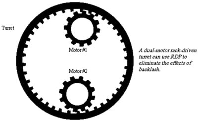
RDP is a velocity control method that allows a positioner to control the two pinion motors as if they were a single, ordinary servo motor. RDP simplifies the control of the rack by automatically taking up backlash during periods of light loads. Here, the motors provide torque in opposite directions to hold the rack in tension or compression. During heavy loads, RDP automatically pulls one motor across the backlash so both motors share the burden. This is especially important during large accelerations where RDP allows both motors to share the acceleration load. This halves the size of the motors required to attain a certain acceleration level or resistance to disturbance torque, as compared to when the motors cannot share the load. At the end of the acceleration, the load naturally decreases and RDP automatically returns the motor through the backlash, holding the rack once again, in tension or compression.
Since RDP provides two integrating velocity loops, when the rack is in tension, loads from either direction are resisted up to the full torque of the motors. RDP ensures that the two loops do not fight each other when the velocity commands to the two drives are slightly different, such as when an offset in an A/D converter injects a slight error. Without this feature, the two velocity loops normally ramp off in opposite directions because the two integrating loops have slightly different commands but are forced (by mechanical linkage) to have identical speeds. Such a loop structure cannot be satisfied until the loops saturate.
The advantages of RDP are:
- Allow virtually any motion controller as well as the drive’s own positon controller to control the two pinion motors as a single motor.
- Eliminate backlash during light loads.
- Allow two drives to share heavy loads, such as during large acceleration.
- Support two integrating velocity loops that do not fight each other.
- Maintain smooth control when a motor crosses over the backlash, avoid banging of gears.
Mechanical System
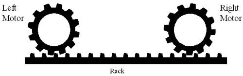
Rack drive systems are commonly used where the travel distances are long. For example, large telescopes and large machining tables are often rack driven. While a ball screw is typically limited to about 2 meters, rack drives are commonly used for more than 10 times that distance. The primary difficulty in controlling rack-driven mechanisms is backlash. The construction of the rack-and-pinion mechanism makes it more difficult to maintain the tight tolerances required to mechanically reduce backlash to acceptable levels. Additionally, because of the relatively low gear ratio of rack-and-pinion mechanisms, they commonly use gearboxes, which add to the backlash. As a result, a drive mechanism is often required to reduce backlash. The most common mechanism is to use two motors that hold the rack in tension or compression.A simplified schematic of the mechanical structure:
A similar structure is sometimes used to drive a large ball screw. Here, one motor is placed at either end of the ball screw. Depending on the couplings used between the motors and the screw, there may or may not be backlash. If there is backlash, an anti-backlash system such as RDP is often required.
At steady-state, the left motor applies a bias force to the right and the right motor applies a bias force to the left. This compression takes backlash out of the system at steady state. When there is a large acceleration force, both drives share the load. In this case, one of the two motors must cross over the backlash to provide acceleration force (torque). At the end of the move, the motor that came across the backlash must return to other side of the rack to take the backlash back out. This requires a specialized control structure.
Rack Drive Servo Loops
A solution for rack-drive systems is to use a process of equalization between two fully-integrating velocity loops. Finally, equalization has been added. Equalization comes in two parts. First, the torque output is the sum of the outputs of the two loops. This assures that the output to both velocity loops is the same (not including the bias current). Second, a PI equalization controller (shown as KP + KI/s) ensures that the two outputs are equal (except for the difference induced by IBIAS). The equalization controller drives the difference of the outputs of the two PI velocity loops to zero, ensuring that the loops do not fight each other.
The RDP structure ensures that one drive comes across the backlash to help the other during periods of heavy loading. This occurs wherever the sum of the two velocity loops is greater than IBIAS.
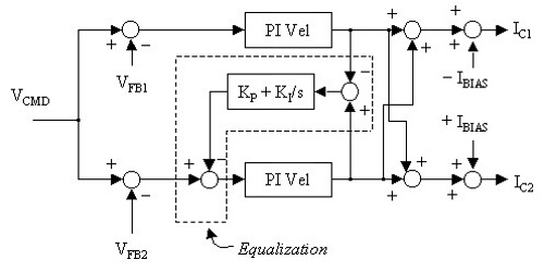
If the sum of the outputs of the two PI velocity controller is greater than IBIAS, IC1 changes from negative to positive. When this occurs, Drive 1 reverses direction and begins aiding Drive 2. Similarly, when the sum of the two velocity loops is less than –IBIAS, IC2 changes sign and Drive 2 aids Drive 1. In both cases, when the load is reduced, the sum of the PI velocity outputs fall below I BIAS, and the system is in tension or compression. IBIAS is a user-configurable variable. It can be set at any level from zero current to the continuous current of the drive. Larger IBIAS has the advantage of increasing the load level up where backlash is eliminated. Unfortunately, larger IBIAS increases power usage and reduces the total peak torque available to the rack.
Once the RDP system is installed and configured, the two axes together behave like a single axis. An external controller only needs to address a single drive. The RDP configuration provides the removal of backlash, the elimination of fighting, and one drive comes across the backlash to aid the other during heavy loads. The external controller can read a position feedback signal and send a velocity or position command to just one drive. The interface between the external controller and the first drive may be a fieldbus or an analog signal or digital I/Os.
In some cases, a separate feedback device connected to the rack may be used.
Expanding the number of drives
If more than two drives are required to provide sufficient torque for an application torque mode drives can be added in pairs. This is possible only in case the external controller is doing the position control and sending analog speed command to two drives in parallel.
For configuration of S700 Drive RDP functionality see RDP - Rack Drive panel
