Home >
 Knowledge Base >
 FAQs >
 Downloads >
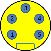
Pinout for (IDC) Stepper motors with quick disconnect
Pin 1 (B+): Red/White (or White)
Pin 2 (A+): Red
Pin 3 (Ground): Green (or Green/Yellow)
Pin 4 (A-): Red/Yellow or Red/Orange (or Purple)
Pin 5 (B-): Red/Black (or Black)
In some cases, the stripes on the wires are not
clearly visible. Check the connections using an
Ohm meter.
The 12-foot stepper motor cable is supplied with the actuators, unless specified otherwise.
The motor connector is mounted on the motor end bell for the larger motors. For the smaller motors, such as P22 and T22, the connector is mounted
on the actuator gear housing. The motor leads exit the face of the motor and run through the gear housing to the connector.
Connector on Motor or Actuator:
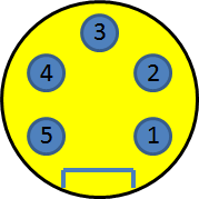
Connector on End of Cable: