Home >
 Knowledge Base >
 FAQs >
 Downloads >
KCM Capacitor Module
Valid for AKD, S300, S400, S601-620, S701-724 @ 400/480 V mains voltage, max. 48A rated output current
General
KCM modules (KOLLMORGEN capacitor modules) absorb kinetic energy generated by the motor when it is operating in generator mode (in the second and fourth quadrants; see Four Quadrant Operation). Normally, this energy is dissipated as waste via brake resistors. KCM modules, however, feed the energy they have stored back into the intermediate circuit as and when it is required.
You can find an approximate calculation of the brake power required in the system here .
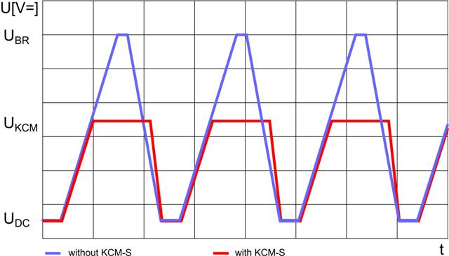
| KCM-S |
Saves energy: Benefits:
|
 |
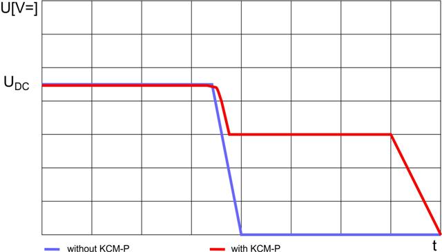
| KCM-P |
Power in spite of power failure: Benefits:
|
 |
| KCM-E |
Expansion module for both applications. Benefits:
|
Technical data
| Dim | KCM-S200 | KCM-P200 | KCM-E200 | KCM-E400 | |
|---|---|---|---|---|---|
| Storage capacity | Ws | 1,600 | 2,000 | 2,000 | 4,000 |
| Rated line voltage | V= | Max. 850 V DC | |||
| Peak line voltage | V= | Max. 950 V DC | |||
| Max. wire cross section | mm² | 6 | |||
| Power | kW | 18 | |||
| Protection type | - | IP20 | |||
| Inception voltage | V= | Calculated | 470 | - | - |
| Dimensions (HxWxD) | mm | 300 x 100 x 201 | |||
| Weight | kg | 6.9 | 6.9 | 4.1 | 6.2 |
| UL Certification | - | UL File E233422 | |||
Documentation / Drawings
- Latest Instruction Manual
- Approvals
- 3D Drawings STEP format (KCM-S, KCM-P, KCM-E)
- Part Number Scheme
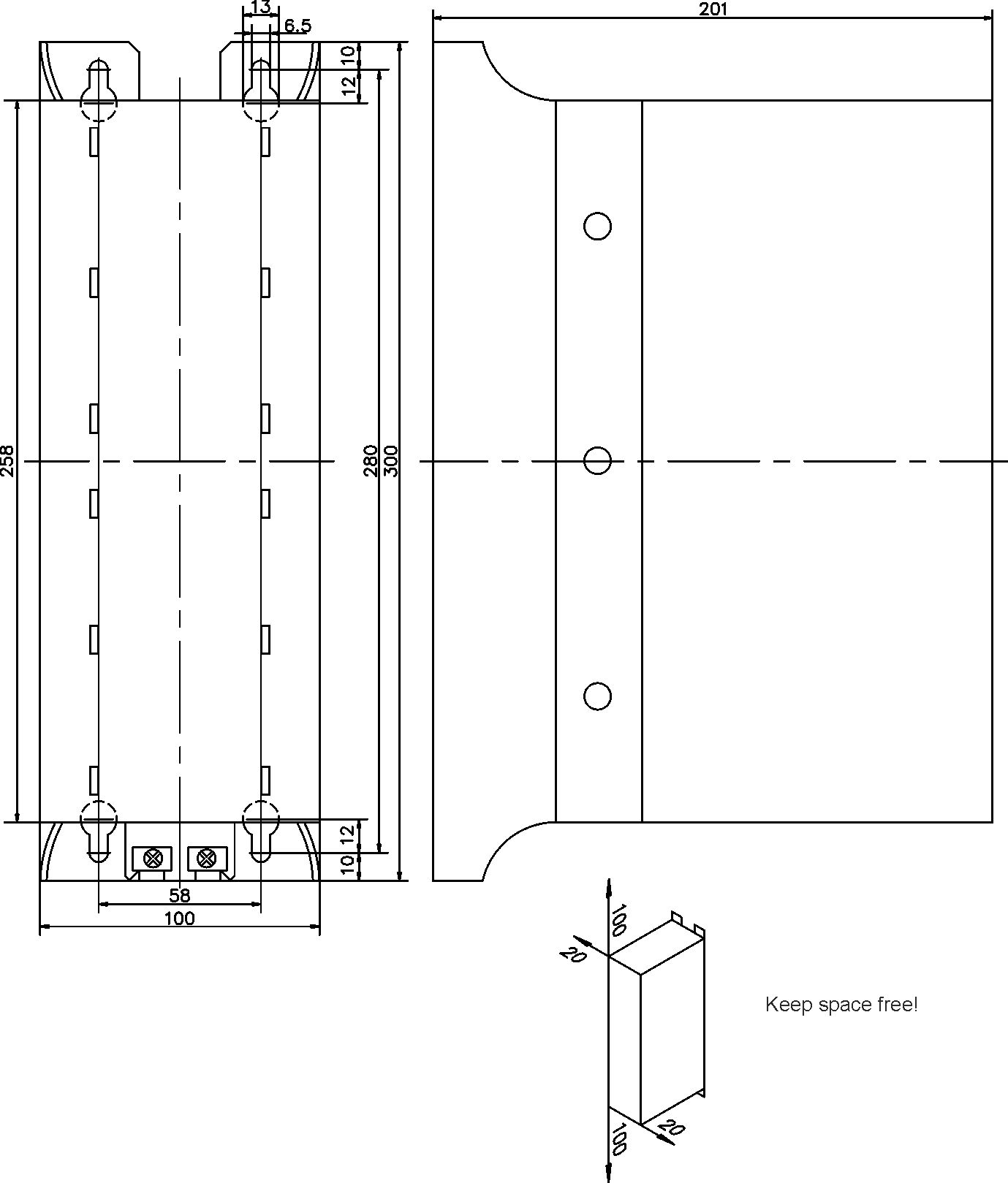
Dimensions
Permissible installation type: vertical; ground connections at bottom; four M6 hexagon head screws.
Make sure there is sufficient unobstructed convection to cool the modules.
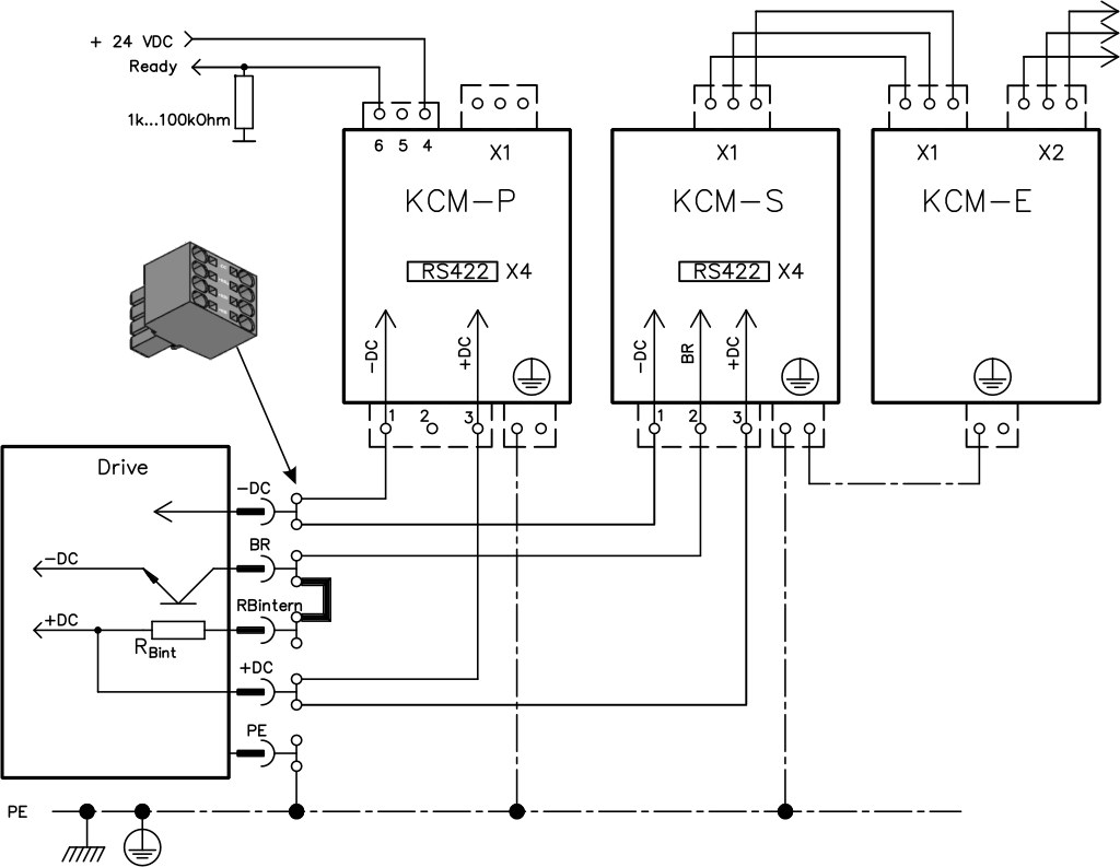
Examples of connection
Maximum line length of 500 mm between servo amplifier and KCM, and between the KCM modules. Twist the lines.
Use shielded cables in case of high level EMC requirements. Further measures may be necessary (see Wiring of KCM with High EMC Requirements).
KCM-S : Connect the BR connection to the servo amplifier with the most frequent regenerative braking processes in the system. This servo amplifier must have an active internal or external brake resistor. For setup, enable the servo amplifier and operate the driving profile that causes the brake chopper to respond. The KCM-S determines the chopper threshold and begins to charge; LED flashes. The energy stored is available the next time acceleration happens.
KCM-P: The KCM-P begins the charging process at approx. 470 V DC; the LED flashes. If the power supply fails, the module provides the servo amplifier with the stored energy that is required to bring the drive to a standstill in a controlled manner (this only applies to the power supply voltage; battery-back the 24 V supply separately). Switch on the line voltage of the system, after the 24V boot process of the servo amplifier has finished.
In a system with one servoamplifier with internal brake resistor, you can use a y-connector to connect the KCM module dirrectly to the servoamplifier:
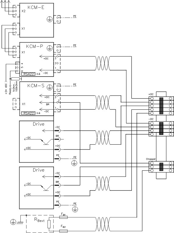
If several servoamplifiers or an external brake resistor is used in the same DC Bus, you should use an additional terminal block:
Serial Interface X4 on KCM-S and KCM-P
Connector X4 (device bottom area) offers a serial interface (RS422) for data exchange on KCM-P and KCM-S. A standard terminal software can be used to transmit/receive the data. The mating connector is part of the package, the cable can be configured by the user.
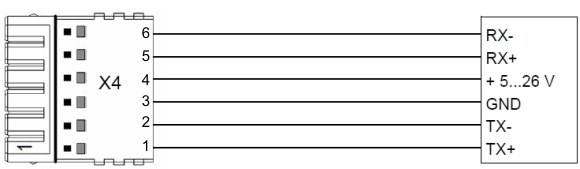
Interface setting in the used PC: 115200 Baud, 8 Data Bits, 1 Stop Bit, No Parity&Flow Control
Parameters which can be accessed via a terminal software:
| Parameter | Dimensions | Meaning |
|---|---|---|
| Status | - | in process |
| U_Zk | V DC | DC Bus link voltage |
| P | W | Average power, this is the equivalent to the minimum power of a brake resistor. |
| W | kWs | Brake energy |
| Wges | kWs | cummulated energy during lifetime |
| X | - | internal data, not relevant |
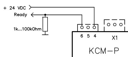
Ready Signal on KCM-P
Terminals 4 and 6 on the top area of the KCM-P can be wired to signal the device load status. With wiring shown below, the output signal is high, if the KCM-P is ready to operate. That means, the voltage level is within a defined tolerance band.