Home >
 Knowledge Base >
 FAQs >
 Downloads >
KAS Modbus RTU Communications (through AKI terminal)
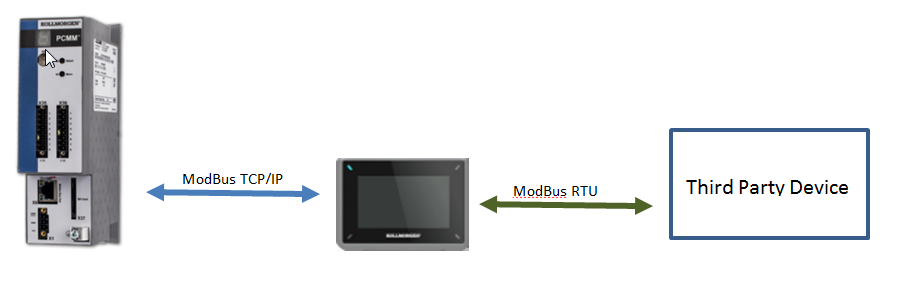
The following procedure outlines setting up Modbus RTU communications between the AKI HMI and a third party device. With a Modbus TCP/IP connection between the PxMM and the same AKI HMI this configuration allows data to be transferred between the ModBus RTU device and the PxMM
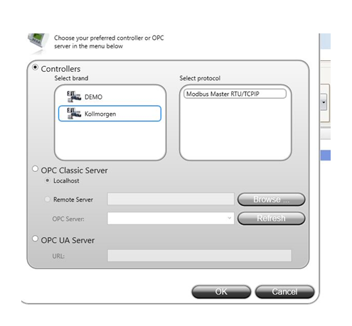
Select “Other Modbus Devices” check box in the IDE Controller Configuration
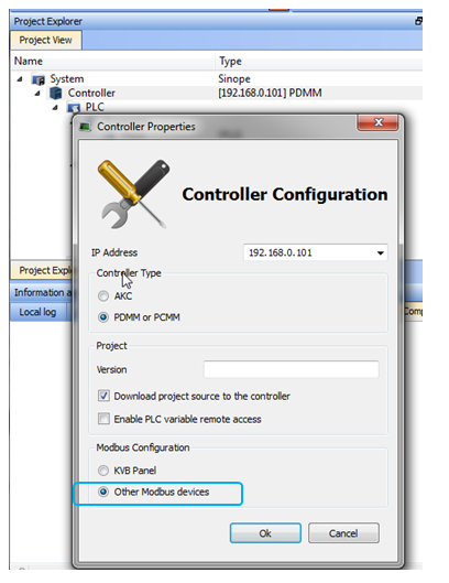
This setting allows creating user settable address in the IDE FieldBus – Modbus Slave screen for the project variables. It is also possible to select “KVB Panel” if the application can use the fixed addresses that are created.
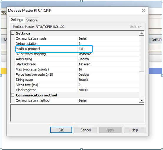
Add Controller 2. Open up KVB inside the IDE project. In the TAGS tab of KVB add Controller 2 for the third party device and configure it as shown. Note this is the same way that the TCPIP port is configured.
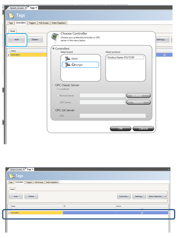
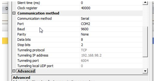
Assign the settings. These will be based on the device you will be communicating with.
The Grayed out items at the end of the communications method section are automatically set by the system.
Define the project variables (tags) -In the IDE Modbus - Fieldbus Setup screen, define the project variables (tags) that will be transmitted over the serial port in the same manner as other variables
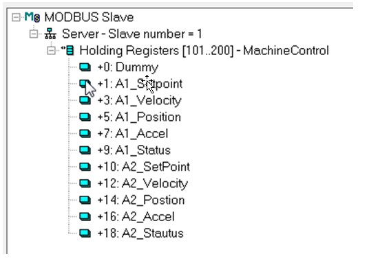
this example register tags start at 101. Add a dummy tag at zero offset to line up the tags numbers with ones in KVB. In example below KVB tag 105 ends up being Actual Temp and KVB tag 106 ends up being A1_Accel.
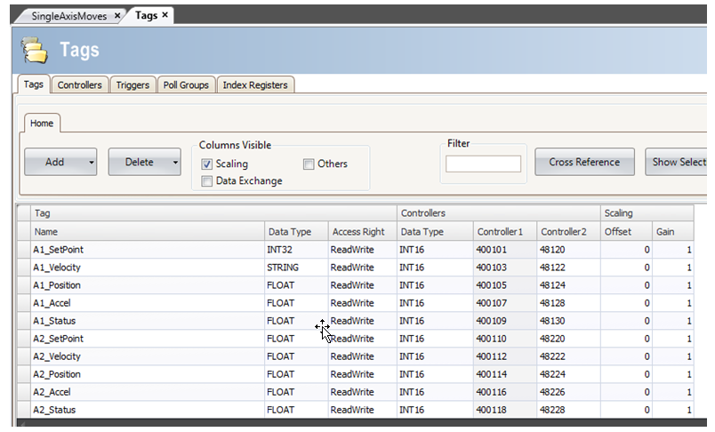
Controller 2 Addresses. Controller 2 column has different addresses. These are the addresses assigned by the third party device that is being connected to the AKI serial port. These addresses will be a function of how the third party devices sets up addresses
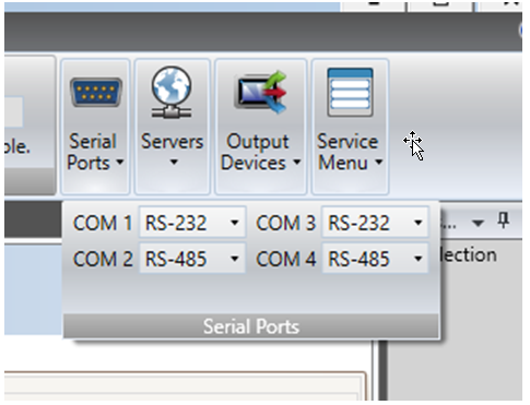
Set up the AKI Serial Port. On the KVB - system tab there is a pull down menu for serial ports. Configure the port for the correct serial coms and connect it as shown below.
Pin COnfiguration for AKI - CDA HMI Terminal