


 Home >
 Knowledge Base >
 FAQs >
 Downloads >
Configuration of PLC Siemens S7-1500 ProfiNetTM and Kollmorgen AKD®2G-SPP
Table of Contents
- System used
- Start a New Project
- Adding the devices
- Configuration of the AKD2G telegram 3
- PLC Configuration
- Profinet Domain Configuration
- AKD2G Configuration
- Program blocks and Technology objects
- Technology objects configuration
- Adding some Functions
- Compiling and Downloading into PLC
- AKD2G status view from Workbench
- About the Attachments
This is a guide to configure the PROFINET IRT communication in between the CPU S7-15xxTx-PN and the AKD2G-SPP PROFINET. The result is to manage both axes by means of the Technology Objects that the PLC provides.
The axes will be configured in Velocity Mode and the PLC will handle the position loop control. For that the ProfiDrive Telegram 3 will be used inside the PROFINET I/O data.
Record of Document Revisions
| Revision | Remarks |
|---|---|
| A 18/03/2021 | First Edition - Preliminary |
Disclaimer:
- All programs in this release (application demos, Kollmorgen UDFBs, etc.) are provided "AS IS, WHERE IS", WITHOUT ANY WARRANTIES, EXPRESS OR IMPLIED.
- There may be technical or editorial omissions in the programs and their specifications.
- These programs are provided solely for Kollmorgen engineer and the user assumes all responsibility for their use. Programs and their content are subject to change without notice.
- This guide doesn’t cover safety aspect of the application which remains a full responsibility of the machine builder.
Trademarks
- AKD2G is registered trademarks of Kollmorgen Corporation
- TIA, S7 are registered trademarks of Siemens AG
- PROFINET is registered trademark of PROFIBUS and PROFINET International (PI)
- All other trademarks are the property of their respective owners
System used
- One drive Kollmorgen AKD2G-SPP-7V03D-A100-0000 (double axis drive), FW M_02-06-00-001
- One Siemens PLC S7-1500 CPU 1511T-1 PN 6ES7 511-1TK01-0AB0
- Siemens TIA Version V16 (Options: TIA Portal Version Control Interface and TIA Portal Openness)
- Siemens STEP7 Professional Version V16 (Options: STEP7 Safety)
- Siemens WinCC Advanced Version V16
- Kollmorgen Workbench Version 2.7.0.5821
- Kollmorgen GSDML file Version GSDML-V2.35-KOLLMORGEN-AKD2G-20201208.xml
- Profinet cable connected in between the PLC Port_1 (X1.P1) and AKD2G Port 1 (X12)
Start a New Project
- Start TIA.
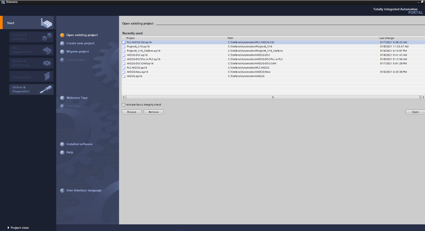
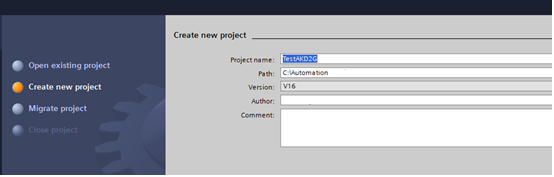
- Click on Create a New Project, enter a Project name, Path, Author, and click on Create (right bottom side)
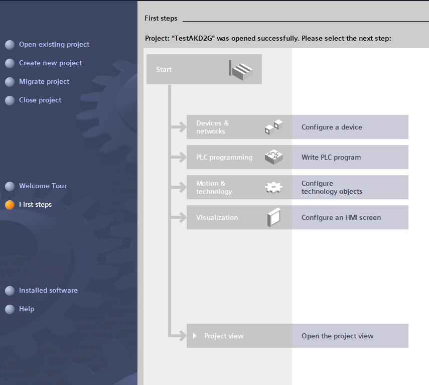
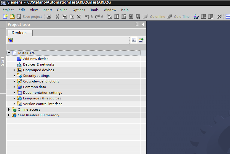
- Go on clicking on Open the project view.
- Next step is to import the AKD2G GSDML file.
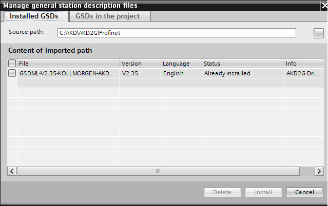
- From the menu Options click on Manage general station description files (GSD)
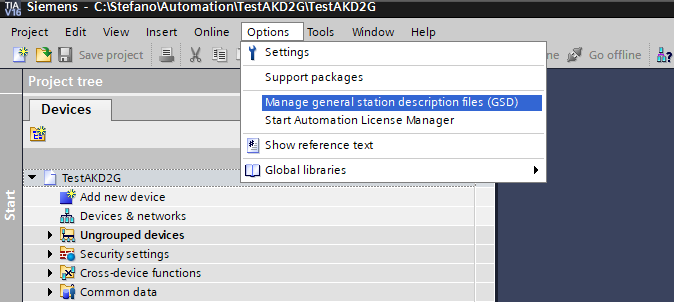
- Install the SGDML file GSDML-V2.35-KOLLMORGEN-AKD2G-20201208.xml
Adding the devices
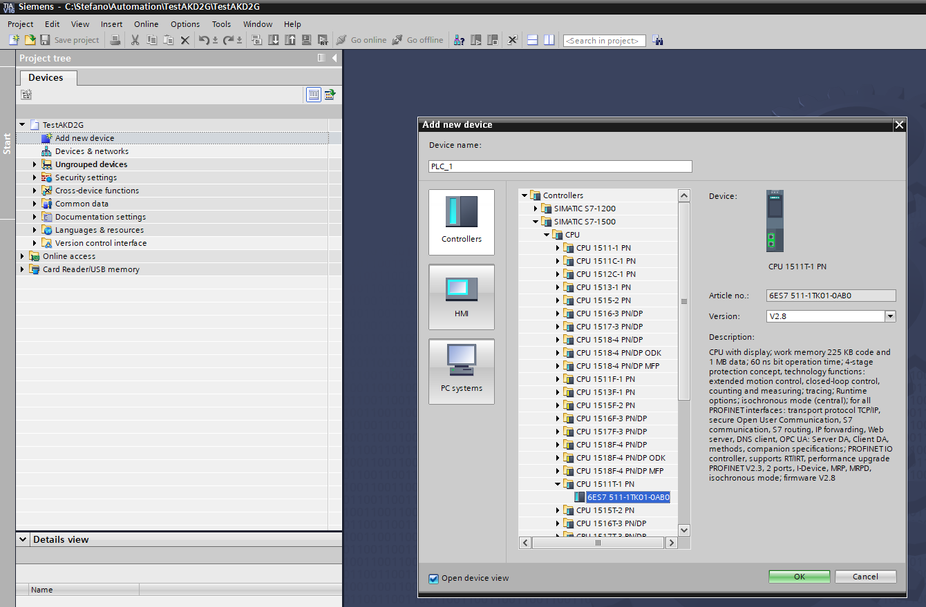
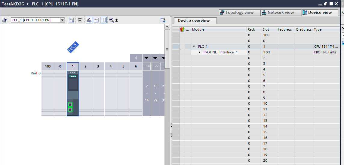
- Click on Add new device and select the CPU model you are using, in this case a S7-1511T-1 PN 6ES7 511-1TK01-0AB0
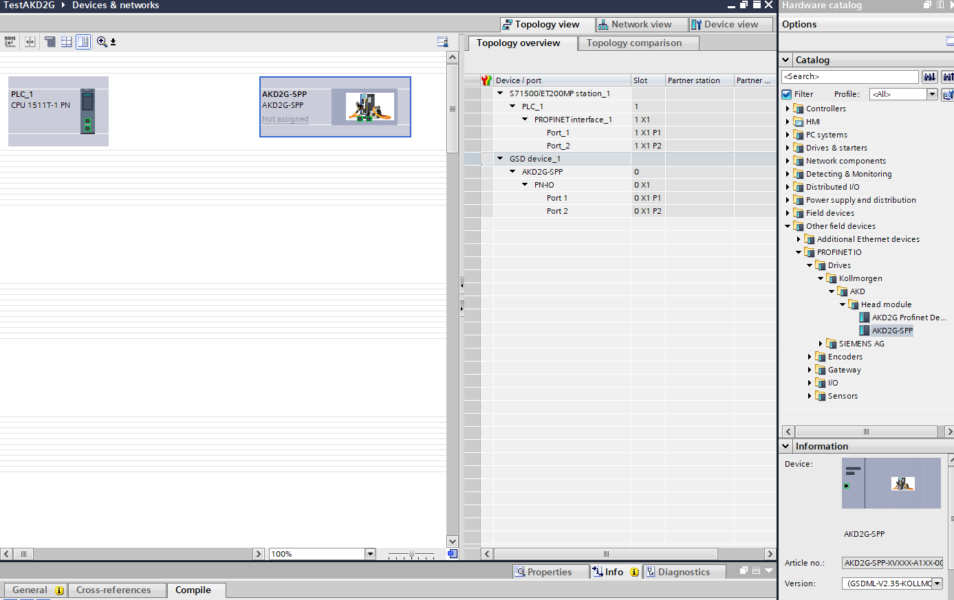
- From the Topology view insert the AKD2G-SPP head module
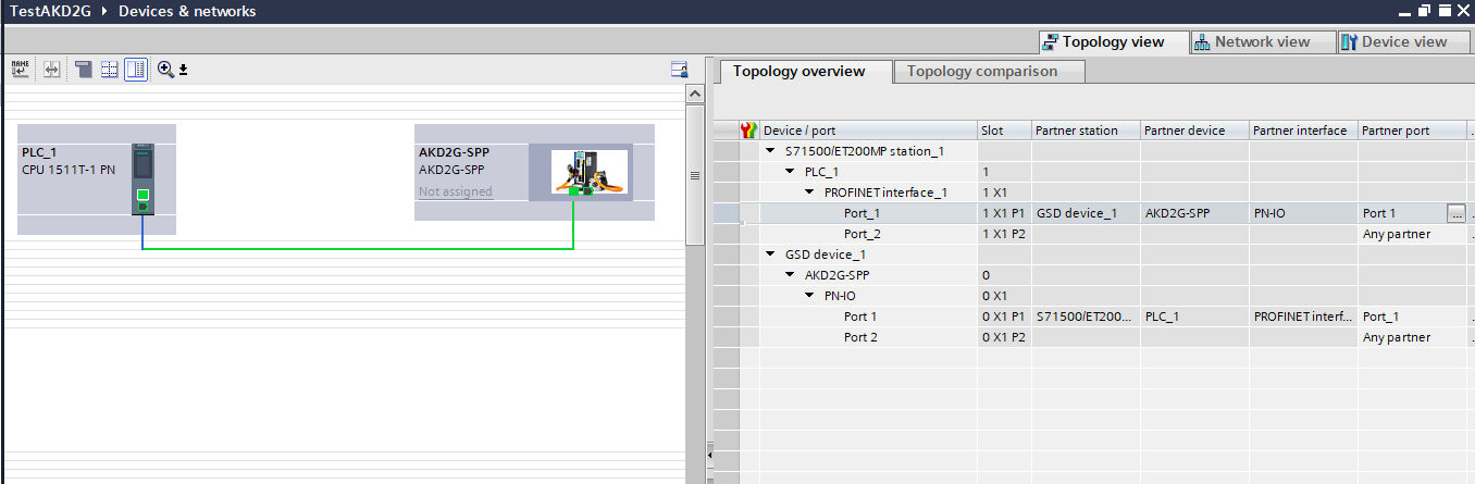
- The Profinet cable is connected in between the PLC Port_1 (X1.P1) and AKD2G Port 1 (X12). Join the ports:
Configuration of the AKD2G telegram 3
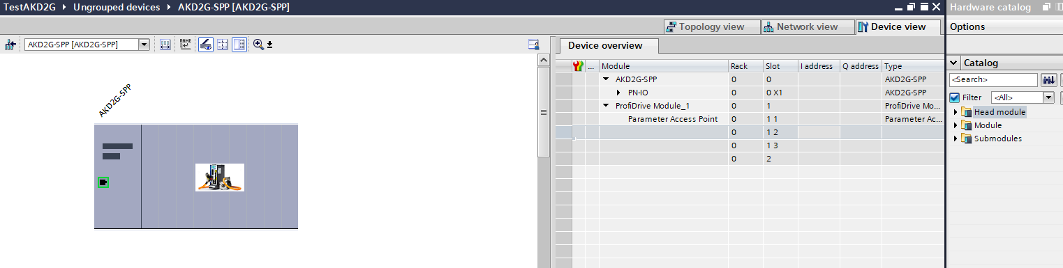
- Double-click on AKD2G device:
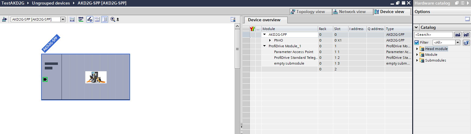
- Delete the ProfiDrive Standard Telegram and the empty submodule from Device overview
- From the right side select ProfiDrive Standard Telegram 3, 5/9 and drag and drop into Device overview:
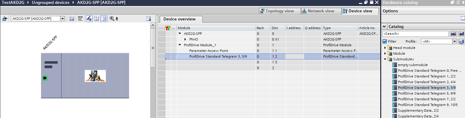
- If the drive is a double axis repeat the operation for the second one.
- Select ProfiDrive Module, drag and drop:
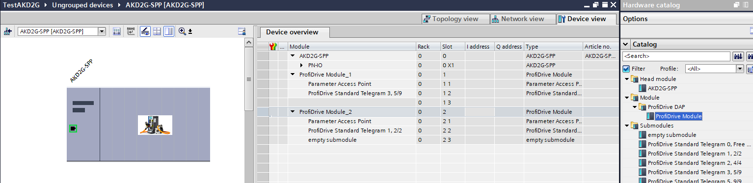
- Delete the ProfiDrive Standard Telegram 1, 2/2 and the empty submodule.
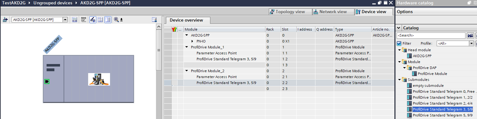
- Then drag and drop the ProfiDrive Standard Telegram 3, 5/9:
PLC Configuration
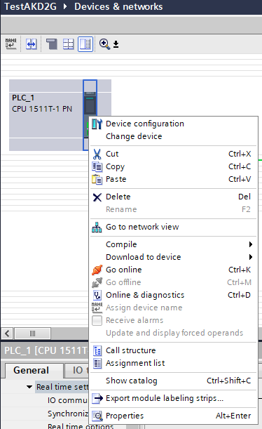
- From the Topology view right-click on the PLC slot and select Properties:
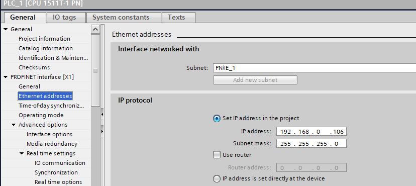
- Set up the PLC Ethernet Addresses:
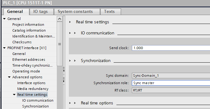
- Set up the Real time settings:
- Send clock: 1ms
- Synchronization role: Sync master
Profinet Domain Configuration
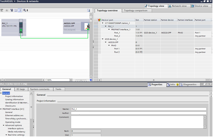
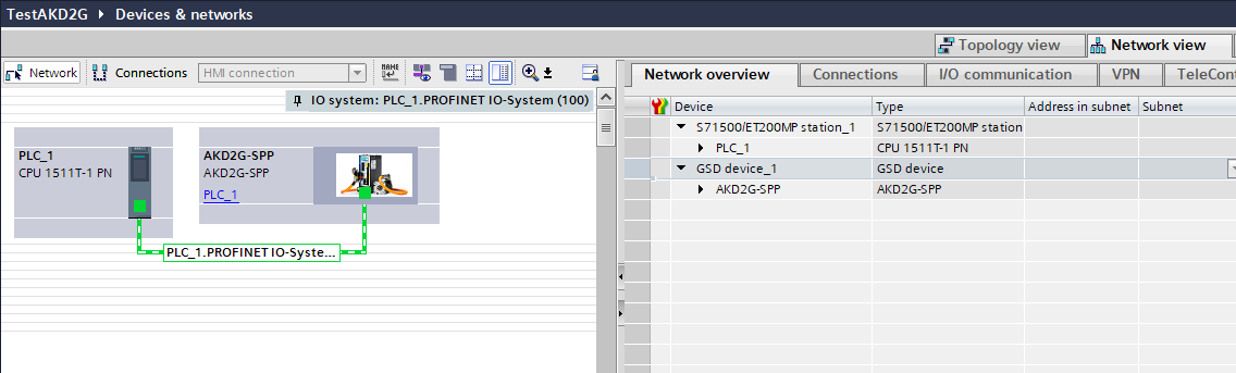
- Go to Network view:
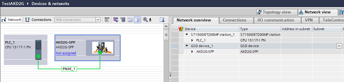
- Click on Not assigned and select PLC_1.PROFINET interface_1:
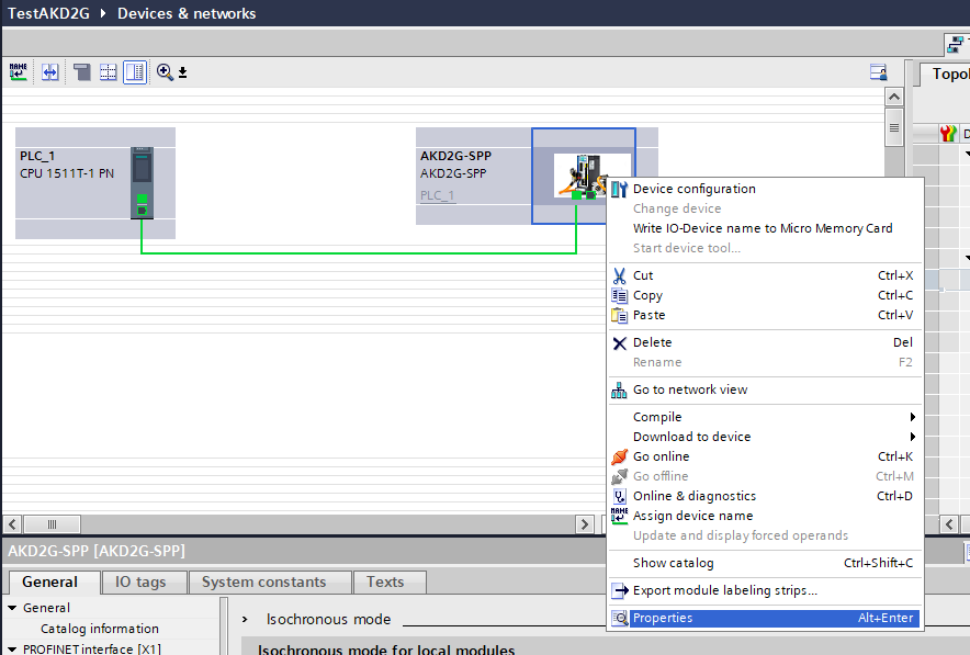
AKD2G Configuration
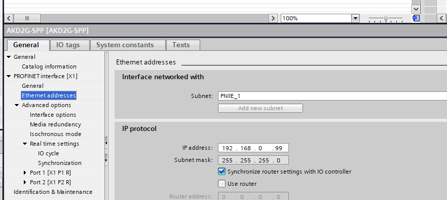
- From the Topology view right-click on the AKD2G slot and select Properties:
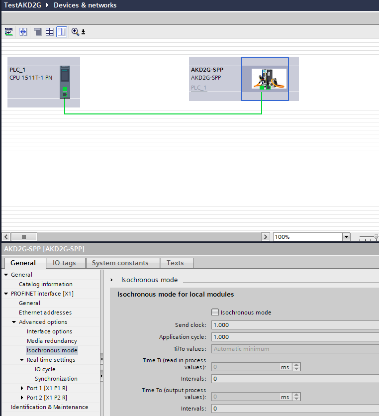
- Set up the AKD2G Ethernet Addresses (this address must be different than IP address of the drive used by Workbench TCP/IP connection):
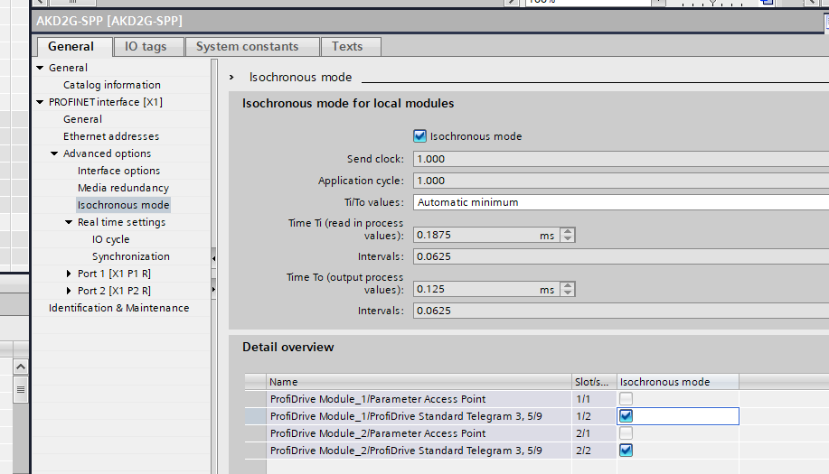
- Activate the Isochronous mode for all the ProfiDrive Modules installed:
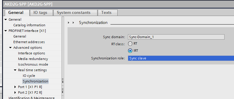
- Set up the Sync domain to IRT:
Program blocks and Technology objects
After the HW configuration the following step is to add the SW function blocks and tech objects for managing the axis.
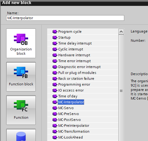
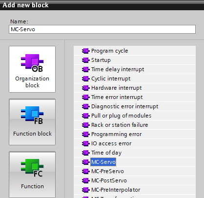
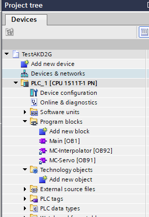
- From Program blocks click on Add new block and add Organization block MC-Interpolator and MC-Servo:
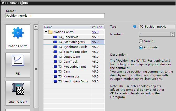
- From Technology objects click on Add new object and add TO_PositioningAxis:
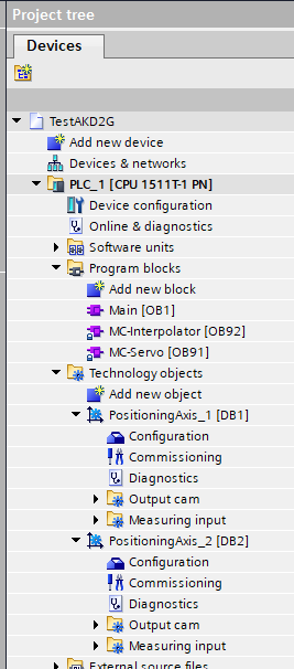
- If you have a second axis repeat this step. At the end we will have:
Technology objects configuration
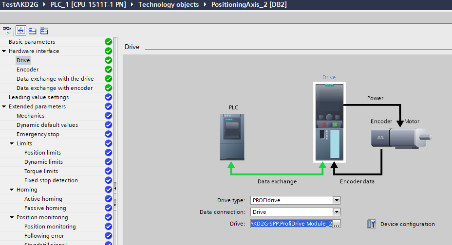
- From the tree view, PositioningAxis_1 select Configuration.
- Apply the following settings:
- Axis type: Rotary
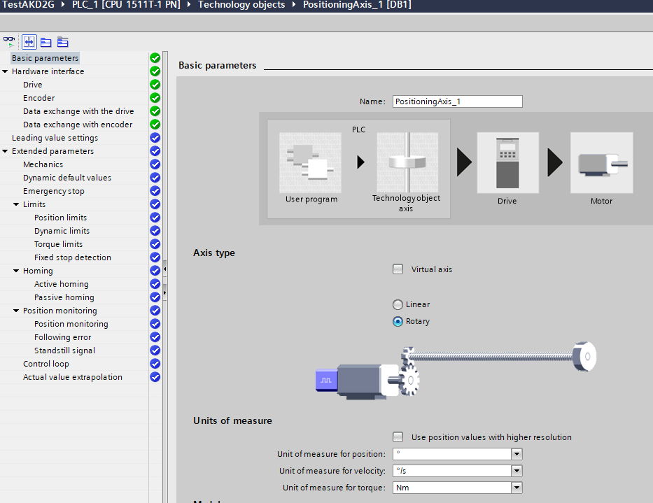
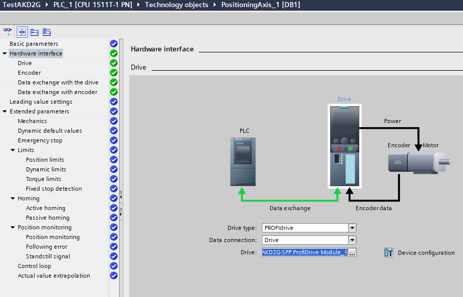
- Drive: AKD2G-SPP.ProfiDrive Module_1
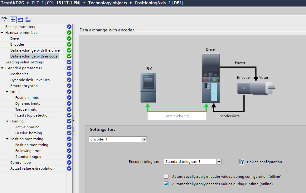
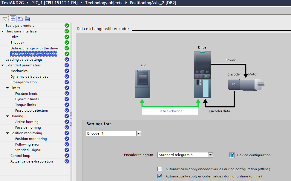
- Data exchange with encoder: Automatically apply encoder values during runtime (online)
- Axis type: Rotary
- If you have a second axis repeat:
- Axis type: Rotary
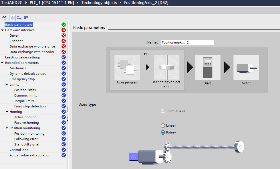
- Drive: AKD2G-SPP.ProfiDrive Module_2
- Data exchange with encoder: Automatically apply encoder values during runtime (online)
- Axis type: Rotary
Adding some Functions
It’s time to add some Motion Functions inside the cyclic OB1. Let’s start with:
- MC_Power
- MC_Home
- MC_MoveRelative
- SinaParaS (read/write AKD2G parameters)
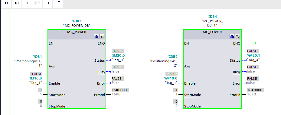
- Open OB1 and add the function MC_Power for all the axes in the project:
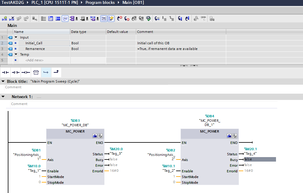
- Pay attention to the inputs Axis of each function: PositioningAxis_1 and PositioningAxis_2 must be passed.
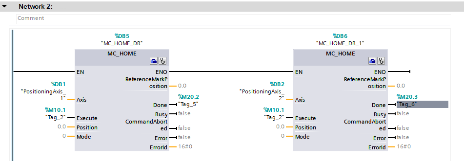
- Add the function MC_Home:
- Add the function MC_MoveRelative:
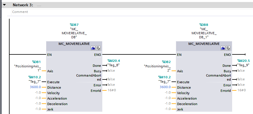
- Because of the PositioningAxis_X setting, the Distance input of 3600.0 makes the motors move 10 turns.
- Add the function SinaParaS:
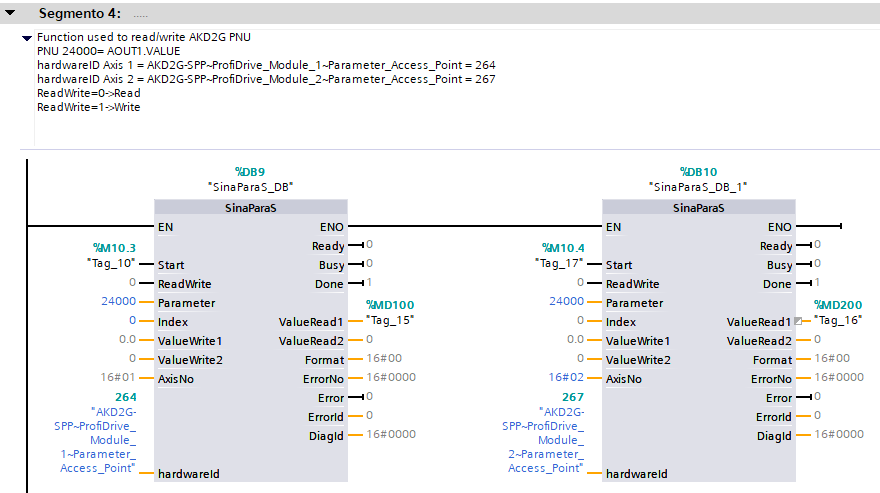
- This function is used to read/write a drive parameter.
In the network above the PNU24000 is the parameter AOUT1.VALUE
Compiling and Downloading into PLC
- Right-click on PLC_1 [CPU 1511T-1 PN], select Compile/Hardware (rebuild all).
- Right-click on PLC_1 [CPU 1511T-1 PN], select Compile/Software (rebuild all).
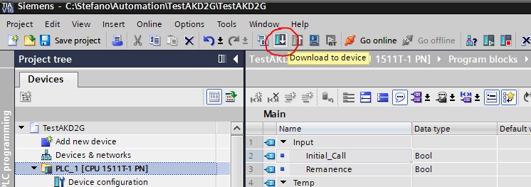
- Click on Download to device:
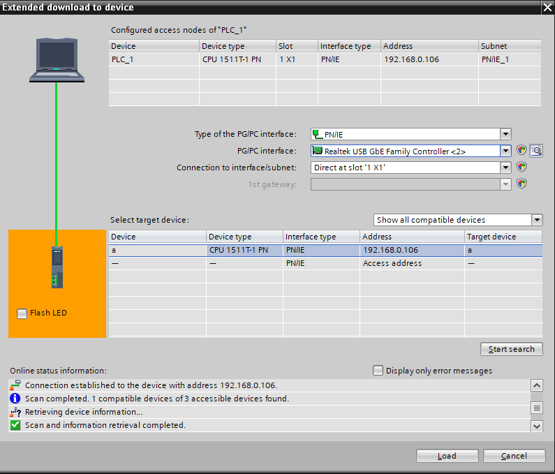
- Select the right PG/PC interface, click on Start search and once found click on Load:
- The first time requires to delete all the modules:
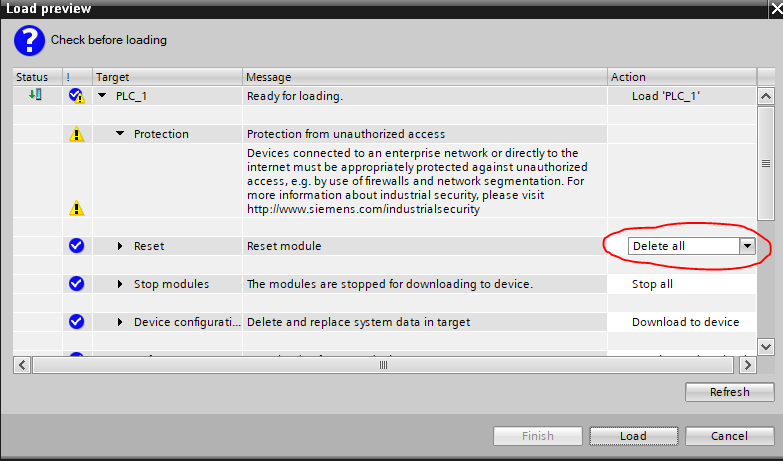
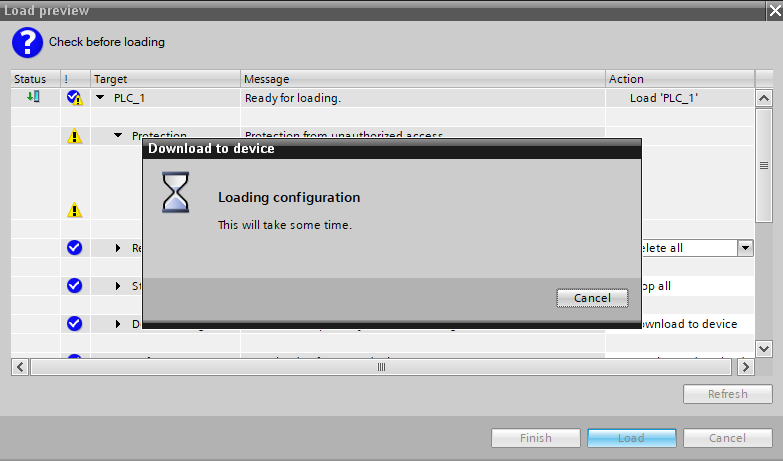
- Go on clicking on Load:
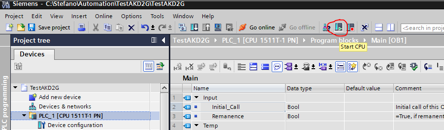
- At the end click on Start CPU:
- Add a new Watch table with some variables:
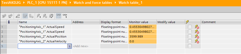
- Going Online with OB1 and changing the markers make it possible to power, home and move the axes:
AKD2G status view from Workbench
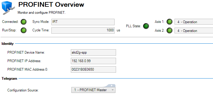
Once the PLC is in run mode, then Workbench can monitor the status.
- Profinet Status
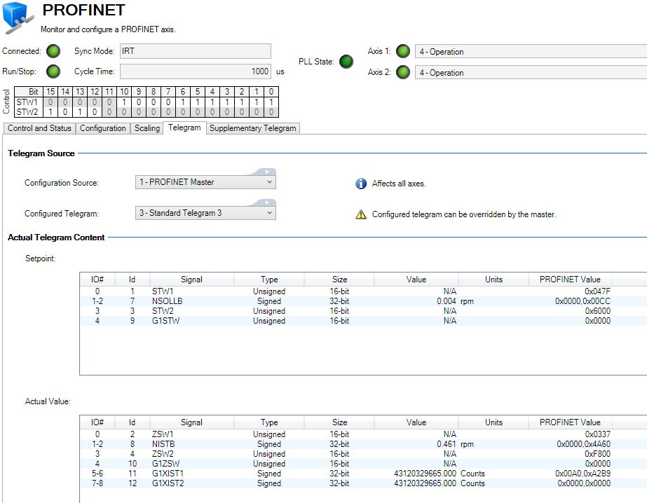
- AKD2G-AXIS 1 status
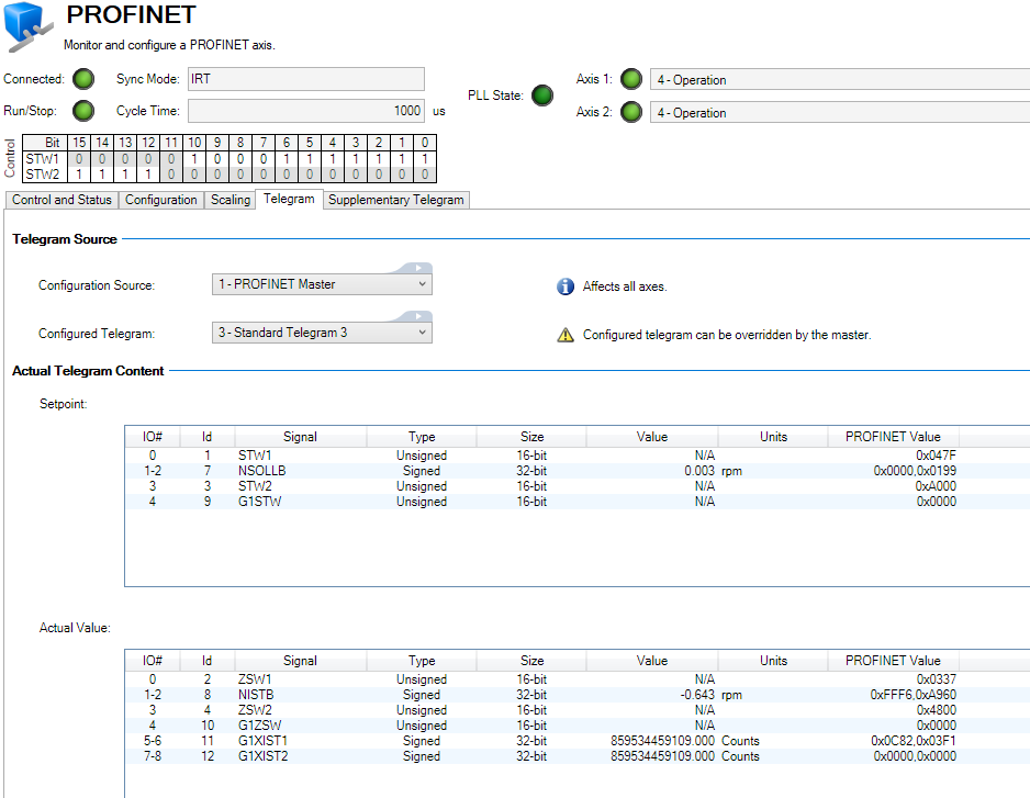
- AKD2G-AXIS 2 status
About the Attachments
Attached to this article are 6 files
- the .DOCX is this article in its original Word format
- the zip files are Zap16 files which are examples of modes of operation.
| Zap16 File | Description |
|---|---|
| S7-1500-AKD2G_MDI-NOIRT | MDI mode in asynchronous mode, no IRT (telegram 9 for both axes) |
| S7-1500-AKD2G-MDI | MDI mode in synchronous mode, IRT (telegram 9 for both axes) |
| S7-1500-AKD2G_MDI-SPEED-NOIRT | First Axis in MDI mode, second in speed mode, no IRT (telegram 9 and telegram 1) |
| AKD2G-DSC-CAM | Example of master-slave by cam profile with DSC, position loop inside the drives (telegram 5 for both axes) |
| TestAKD2G | Position loop close inside the PLC (telegram 3 for both axes) |
Back to top
