


 Home >
 Knowledge Base >
 FAQs >
 Downloads >
Using the MMC-SD Oscilloscope
This article refers to G&L PiC application note document AN000050 and provides information on the oscilloscope function found in the PiCPro Drive Maintenance tools.
Scope
This Application Note applies to the MMC-SD family of products.
Purpose
This Application Note provides information on the oscilloscope function found in the PiCPro Drive Maintenance tools.
Introduction
The oscilloscope is a powerful tool for both setting up and troubleshooting the drive and motion controller. With it, up to 4 channels of information can be seen at one time. The time base can be free running or it can be triggered by another signal. Scope traces can be stored in a format that allows them to be imported in to a spreadsheet or they can be reopened in the Oscilloscope itself for analysis. Setups for the channels and time base can also be saved and restored for common situations such as tuning or troubleshooting.
The oscilloscope operates by capturing data over the PiCPro connection and so there will be delays in its operation. The trace is drawn by connecting the sampled points. Using the Trigger mode, the samples are taken at the rate specified. When running continuous non triggered mode, the sample rate is not in effect. The samples are taken when PiCPro has time available and are much longer – 150 to 200 ms is not uncommon - and are not related to the Selected Sample rate.
Because of these factors, care must be taken in interpreting the oscilloscope data, particularly at points where it is changing dramatically – remember that it is not a continuous analog trace of the signals.
Time Base Operation
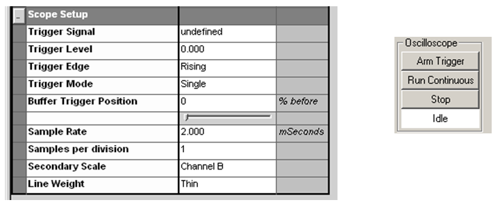
The Scope Setup choices are used in conjunction with the Oscilloscope trigger settings to select the method of operation required.
Run Continuous will cause the oscilloscope to sample and display at intervals that may run in to several hundred milliseconds.
Using the Trigger Signal, Level, Edge and Mode fields in conjunction with the Arm Trigger button will cause the oscilloscope to capture the information selected in each of the 4 channels. The total amount of data captured on each trigger will be 300 – 32 bit words. Most items that can be captured are 32 bit word size. However, actual and command positions will be double (64 bit) words and so will reduce the number of samples that will be taken. So there are trade offs between the resolution and length of time of the capture and the data to be captured.
If two channels such as command and motor velocity are being captured at a 2 ms sample rate, then the length of time able to be caught will be (300 / 2) x 2 ms = 300ms.
The interval for Triggered modes only is set in the Sample Rate field. It can be from 0.125 ms to 8192 ms.
So if you want to capture 2 channels of data for a 1.5 second (1500 ms) move, then the sample rate would be a minimum of 1500 ms / (300 / 2) = 10 ms.
Hiding selected channels does not stop them from being captured and using up capture data memory. A channel must be made Undefined to stop it being captured.
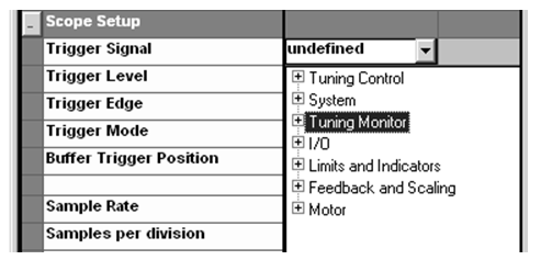
The Trigger signal is selectable from a list of drive signals.
The level of the required trigger signal can be set and the direction of the trigger signal can be rising, falling or immediate. The Immediate choice will cause a capture to be made when the Arm Trigger button is clicked.
The trigger mode can be Single or Continuous. Choosing Single will cause the oscilloscope to make one capture and then stop. Selecting Continuous for the Trigger Mode gives the advantages of Continuous Mode, in that the oscilloscope keeps updating, and triggered operation, in that the trace appears on the screen in the same place each time.
The Buffer Trigger Position allows the display to show events that occur by the % chosen before the trigger occurs.
The Samples per Division selection affects the display only. It can be changed after capture if required to compress or extend the time displayed on the screen. It can be set to 1, 2, 5 or 10 samples per display division. Setting this to 10 initially will compress the capture in to less screen space and makes for easier assessment of whether the other choices are correct.
Choose the Medium selection under line weight for better trace visibility. If you are capturing items that have different units such as velocity in RPM and current in amps, then set the Secondary Scale to one of the items. Its units will then appear on the right hand vertical axis of the oscilloscope.
Channel Selection
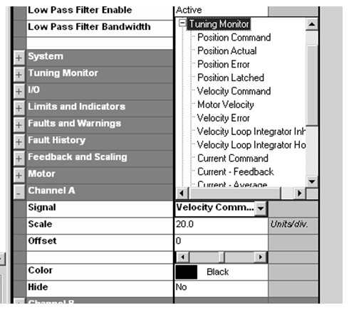
Up to 4 channels of data can be displayed. The Signal field allows selection from items in several categories. Choose the one required and set the scale if known. The scale may be changed after capture or while running continuously. Each channel has a default color, but this can be changed if desired. The Offset allows the trace for a channel to be shifted vertically on the oscilloscope trace. This may be done for separation of traces for better viewing, or to allow values such as position that have a wide range to be brought into a range that allows viewing on a smaller scale with finer resolution.
A channel can be selected but not displayed by select YES in the Hide field. However, it will still be captured in the Trigger mode and use up some of the 300 memory words available. A signal can be deselected from a channel by clicking on the Signal field so the pull down arrow shows, and pressing the keyboard Delete key. The field should then show Undefined.
All the fields except the Signal field can be changed and will take effect immediately, both while the oscilloscope is running and after it has captured a trace.
Once the Setup and Channel selections are made, they can be saved under File – Save Scope Template and later brought back using File – Recall Scope Template.
Traces may also be saved using File – Save Trace and restored using File – Restore Trace. Saved files may also be imported in to Excel or other spreadsheet and then charted.