Home >
 Knowledge Base >
 FAQs >
 Downloads >
Operating Induction machines in AKD, using a closed-loop field oriented control
Firmware version: M-01-12-01-000
This article explains how to set an AKD for driving an asynchronous machine, using a closed-loop field oriented control (FOC) strategy. The article contains:
Introduction
A Field Oriented Control (FOC) strategy to control an asynchronous machine is implemented in AKD. A separate control of flux and torque is possible, similar to a DC-machine. Fig 1 shows the implemented scheme.
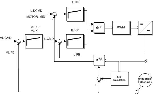
Figure 1: Field Oriented Control of an ASM
The velocity command can be obtained from three different sources, depending on DRV.CMDSOURCE
- 0: Service
- 1: Field bus
- 3: Analog
Initial settings
| DRV.OPMODE = 1 | Velocity mode |
| MOTOR.TYPE = 4 | V/Hz speed control |
| FB1.SELECT = XX | Select according to your feedback |
| DRV.ACC & DRV.DEC | Set according to induction machine mechanical dynamics |
Parameters
The following table shows which MOTOR parameters should be also configured for driving induction machines under FOC closed-loop operation:
|
Keyword |
Induction Motor Closed Loop |
Description |
|
MOTOR.NAME |
Yes |
Set a name for customer motor |
|
MOTOR.TYPE |
Yes |
Set to motor type. For V/Hz, MOTOR.TYPE = 4 |
|
MOTOR.AUTOSET |
Yes |
Available for FOC |
|
MOTOR.IPEAK |
Yes |
Set to motor peak current (A). 150% of continuous current for NEMA motors |
|
MOTOR.ICONT |
Yes |
Set to motor continuous current (A) |
|
MOTOR.INERTIA |
Yes |
Set the motor inertia in kg cm2 |
|
MOTOR.KT |
No |
No necessary for Induction Motor |
|
MOTOR.LQLL |
Yes |
Set the stator inductance in mH. For further information see below section “calculation of machine parameters”. |
|
MOTOR.POLES |
Yes |
Set to motor poles |
|
MOTOR.VMAX |
Yes |
This is the maximum mechanical speed of the motor in RPM |
|
MOTOR.R |
Yes |
Set the stator winding resistance phase-to-phase in Ohms. For further information see below section “calculation of machine parameters”. |
|
MOTOR.VOLTMAX |
Yes |
Motor max winding voltage. Ex: 230 VAC or 460VAC |
|
MOTOR.PHASE |
No |
No necessary for Induction Motor |
|
MOTOR.CTF0 |
Yes |
This is used to configure the thermal constant of the motor coil |
|
MOTOR.KE |
No |
No necessary for Induction Motor |
|
MOTOR.IMTR |
Yes |
Set the rotor time constant in ms. For further information see below section “calculation of machine parameters”. |
|
MOTOR.IMID |
Yes |
Set the magnetizing current (id) in A. For further information see below section “calculation of machine parameters”. |
|
MOTOR.VOLTRATED |
No |
No necessary for FOC |
|
MOTOR.VRATED |
No |
No necessary for FOC |
|
MOTOR.VOLTMIN |
No |
No necessary for FOC |
Field weakening.
So far, the closed-loop control implemented in AKD is not able to drive the ASM in field weakening area.
Calculation of machine parameters
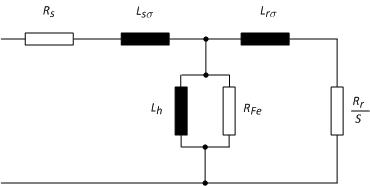
Figure 2: Induction motor equivalent circuit
1. Determine current set point id = MOTOR.IMID
The direct-axis (non-torque axis) current Id is set to a constant value as soon as the drive is enabled. MOTOR.IMID is used to set up and view the magnitude of Id set point.
The appropriate value of MOTOR.IMID can be estimated from the motor nameplate information.
A rule of thumb as follows can be used (see S300 manual):
|
|
1 |
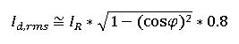
In which Id is the value for MOTOR.IMID, the preset rotor flux building current. IR and cos(phi)are the phase current and power factor at rated operation, read from the motor data sheet respectively. And 0.8 is an empirical factor. MOTOR.IMID is in Arms.
2. Rotor resistance
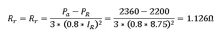
The rotor resistance can be calculated based on the electrical motor losses. This means, based on the difference between ideal mechanical power and real mechanical power, the rotor resistance can be calculated as follows:
|
|
2 |
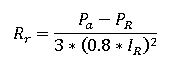
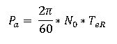
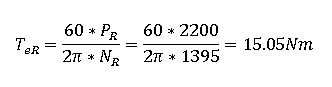
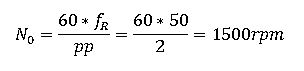
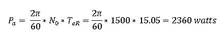
Where Pa is the ideal mechanical power, N0 is the synchronous speed and TeR is the nominal electromagnetic torque defined as:
|
|
3 |
|
|
4 |
|
|
5 |
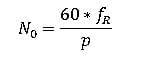
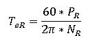
PR, IR, fR and NR are the nominal values for power, current, frequency and speed, read from motor data sheet, respectively.
3. Rotor inductance
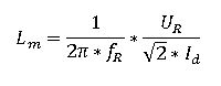
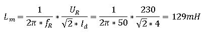
The rotor inductance is defined as LR = Lm + Lró. Since Lm is bigger than Lró, we consider that: Lr = Lm. The mutual inductance can be calculated as follows:
|
|
6 |
4. Rotor time constant
Finally, the rotor time constant is calculated as follows:
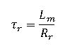 |
7 |
Vector current limiting
1. Id limits:
- Upper limit: 93.75% fold-back current limit, which is calculated as the smallest of drive current limit, motor current limit, and what fold back algorithm allows.
- Lower limit: -93.75% fold-back current limit.
2. Iq limits:
- Upper: the lower of
- Sqrt(Ifold^2 – Id^2)
- User set Iq positive limit
- Lower: the higher of
- Sqrt(Ifold^2 – Id^2)
- User set Iq negative limit
Commutation angle setting
For induction motor closed loop control the commutation angle is set as shown in the following figure:
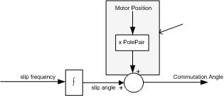
Figure 3. Commutation angle setting in AKD for IM
Induction motor close loop control supports using FB1 or FB2 as commutation feedback source. The shaded calculation, adding motor position feedback to the slip, happens in the FPGA if using FB1 IL.FBSOURCE 0; and in firmware if IL.FBSOURCE is 1
Variables for analysis
Following variables are available for analysis and supervision:
|
IL.CMD |
Currently reference for iq (torque-generation current) |
|
IL.FB |
Currently current for iq, at motor terminals |
|
IL.IDCMD |
Currently reference for id (flux-generation current) |
|
VL.CMD |
Velocity reference |
|
VL.FB |
Shaft position, read from the feedback |
Further Information
Such concept is also implemented for our Servostar amplifier. You can find more information in the following links:
Sensorless Control for Induction Machines with S300-S700
Operating Induction Machines S300-S700
Example
Considering the following ASM:
|
Nominal voltage = 230/460V |
Nominal current = 8.75/5.05A |
4 poles |
|
Power: 2.20Kw |
Nominal speed = 1395 rpm |
|
|
cos(phi) = 0.82 |
Nominal frequency = 50Hz |
|
With a resolver as feedback
Then, the missed machine parameters are calculated as follows:
- MOTOR.IMID: based on equation 1:
![]()
- Rotor resistance. The nominal electromagnetic torque is calculated based on eq. 5:
Based on eq. 4, we got the synchronous speed as:
The ideal mechanical power from eq. 3 is:
From eq. 2, the rotor resistance is then calculated as:
- Mutual inductance. From eq. 6, we got:
- Rotor time constant. Finally from eq. 7
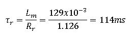
We set following parameters in AKD
|
Parameter |
Value |
Parameter |
Value |
|
DRV.ACC & DRV.DEC |
10000rpm/s |
MOTOR.POLES |
4 |
|
DRV.OPMODE |
1 |
MOTOR.VMAX |
1600 rpm |
|
FB1.SELECT |
40 |
MOTOR.R |
1.126 ohm |
|
MOTOR.NAME |
NORD-ASM |
MOTOR.VOLTMAX |
240V |
|
MOTOR.TYPE |
4 |
MOTOR.IMTR |
114 ms |
|
MOTOR.IPEAK |
13 A |
MOTOR.IMID |
4 A |
|
MOTOR.ICONT |
8.75 A |
|
|
|
MOTOR.INERTIA |
6.2 kg cm2 |
|
|
|
MOTOR.LQLL |
129 mH |
|
|
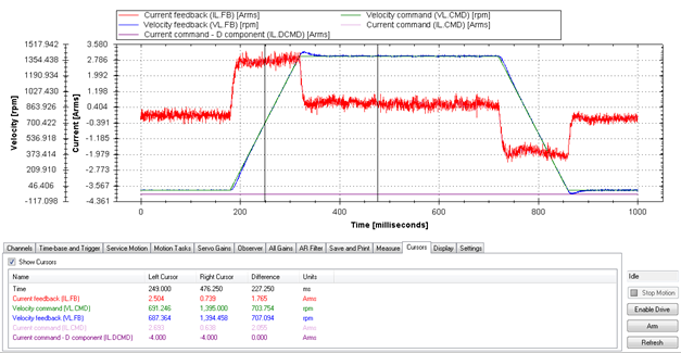
Speed command: 1395 rpm