


 Home >
 Knowledge Base >
 FAQs >
 Downloads >
FPGA Based Sin Cos Encoder Processing
Source PCIM 2007:
FPGA Based Sine - Cosine Encoder Feedback Processing for Servo Drive Applications
Introduction
High performance servo drives are still a fast growing market segment. High resolution encoders are commonly used as motor position sensing device, fig. 1. Also, most modern controllers derive velocity feedback from the position sensor. The conversion of sine-cosine-encoder signals to measure position is more and more accomplished within the encoder. Due to a digital link to the drive long cables with fewer wires do not limit the maximal signal frequency and do not reduce the feedback signal quality.
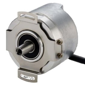
Fig. 1: Hengstler sine cosine encoder AD 58-BiSS {1]
Most servo drive designers are not willing to design in special dedicated chips. Modern drives usually feature Field Programmable Gate Array (FPGA) area reserved to realize digital interface logic. This logic configuration is usually able to cover several digital feedback interfaces.
Sine-cosine encoders are an extension to standard A quad B encoders. For the manufacturers it is much easier to design optical encoders with sinusoidal signals than TTL encoders with very high line numbers.
The operating principle is that the subsequent electronics counts the sine waves and also performs tan-1 fine interpolation within one signal period, fig 2.
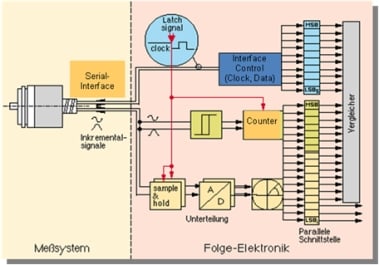
Fig. 2: Decoding sinus cosine encoder signals with a counter and tan-1 fine interpolation
Offset and Gain Error
The position resolution and the position error within one signal period are the most relevant factors for fine interpolation. The selection of the encoder technology is strongly dependent on the accuracy requirements of the respective application.
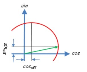
Fig. 3: Sine cosine offset error
The measured angle ![]() from a sine cosine encoder with tan-1 fine interpolation is the sum of the real angle φ and an additional interpolation error
from a sine cosine encoder with tan-1 fine interpolation is the sum of the real angle φ and an additional interpolation error ![]() :
:
![]()
The offset and gain interpolation error depends on:
cosoff: cosine signal offset
rcos: cosine signal amplitude
sinoff: sine signal offset
rsin: sine signal amplitude
n: sine cosine lines per revolution (usually 512 or 2048)
With no significant errors (Taylor approximation) the interpolation error ![]() can be calculated by:
can be calculated by:
![]()
Using 1 Vss encoder signals rcos and rsin are ~500 mV. One percent (5 mV) offset (cosoff and sinoff) and n = 512 lines per revolution are also reasonable values. Due to a gain error rcos can be one percent greater than rsin :
![]()
![]()
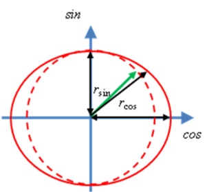
Fig. 4: Sincos gain error
The maximum angle error ![]() with the used offset and gain error is:
with the used offset and gain error is:
![]()
This offers a maximum of 17.3 bit resolution per revolution due to the gain and offset error. Where 9 bit come from the counter (n) and additional 8.3 bit are achievable due to the tan-1 fine interpolation. In case of higher requirements an encoder with more lines per rev and/or an extended fine interpolation with on-line gain and offset adjustment are necessary.
In most cases the bottleneck of the system is not the position precision. Most servo systems derive the more critical velocity feedback signal from the measured position signal with an observer:
![]()
To examine the velocity error ![]() it is enough to derive the position error:
it is enough to derive the position error:
![]()
![]()
and ![]()
We get ![]()
After some math we get an equation for the relative speed error:
![]()
Not Synchronous Sampling Error
Not exactly synchronous sampling of the two channels generates also an additional position error: For a mathematical analysis the cosine signal is viewed as delayed with the delay time TD. This shows the same behavior like sampling the cosine signal TD earlier compared with the sine sampling time. This is degenerating the circle to an ellipse with 45° rotated axis, Fig. 5.
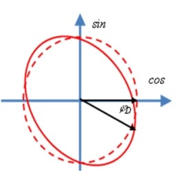
Fig. 5: Cosine delay error
At zero speed the encoder signal is constant and so the delay TD does not matter. In case of a rotating motor with the encoder signal frequency ![]() the delay time generates a speed proportional phase shift of the cos signal:
the delay time generates a speed proportional phase shift of the cos signal:
![]()
This phase lag causes a velocity dependent position error:
![]()
And a velocity error:
![]()
Rotating a 2048 line encoder with n = 3000 rpm generates a fE = 50 Hz * 2048 = 102.4 kHz encoder signal frequency. A delay time of only 15.6 ns generates a phase lag of:
![]()
![]()
And also a one percent (high speed) velocity error:
![]()
Looking at these equations we conclude:
- 1% offset on the encoder sine and/or cosine signal forces a 1% velocity error with encoder signal frequency.
- 1% gain error between the signals forces a 1% velocity error with double encoder signal frequency.
- 0.01 radiant phase error between the signals forces a 1% high speed velocity error with double encoder signal frequency.
Analog to Digital Conversion Error
ADC based offset and gain errors do not need a separate review. These errors are handled together with the analog encoder offset and gain error. With a 12-bit analog to digital converter (industry standard) the quantization noise is about ±0.05 % (100 % / ±2048). There are two ways to reduce this noise:
- Select higher resolution ADC (higher SNR
- Take advantage of Oversampling technique
Due to the noisy environment inside a servo drive the use of a higher resolution ADC is not trivial. Setting a low pass filter is more or less not possible because of the high frequency encoder signals (>250 kHz).
Usually the encoder position is required with the feedback loop update frequency:
- The current controller uses the commutation (low resolution is ok)
- The velocity controller needs a speed feedback signal (position derivative)
- The position controller requires a position feedback signal
This update frequency is usually related to the power stage switching frequency. In a servo drive with fs = 8 kHz switching frequency is the fastest current loop update (sample) time usually T0 = 62.5 µs.
Sampling itself is also an important issue. If the encoder frequency is near or higher than the sampling frequency the speed error amplitude is damped to a lower value with a different frequency (aliasing), fig 6.
![]()
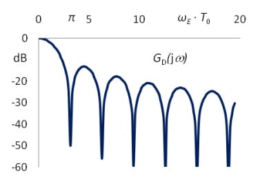
Fig. 6: Encoder frequency ωE and sample time T0 velocity ripple damping function
The position error is not affected by the sample time.
If the system is powerful enough to process the encoder signal several times within one servo loop update time the quantization noise can be significantly reduced by Oversampling, Fig. 7.
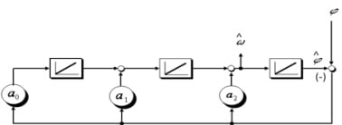
Fig. 7: Position signal filter (with Oversampling)
Oversampling by utilizing flash ADCs and FPGA based digital signal processing with a sampling rate of 16 MHz and more is realistic. Fig. 7 shows the block diagram of a third order velocity observer. The position j is calculated with an update rate of 16 MHz. This position is compared with the estimated observer position ![]() . The difference is used as observer feedback signal. In fact the observer is acting like a low pass with minor phase lag if the acceleration
. The difference is used as observer feedback signal. In fact the observer is acting like a low pass with minor phase lag if the acceleration ![]() is not constant:
is not constant:
![]()
By setting this low pass cut off frequency to 50 kHz (with a0 , a1 , a2) the quantization noise can be reduced by approximately 20 dB:
![]()
This boosts a 12-Bit ADC up to 15-Bit SNR performance. Another option is to use the DSP capability of the FPGA to execute an on-line offset and gain adjustment.
Due to the Oversampling technique the Kollmorgen S700 Servo Drive is offering outstanding performance in processing analog sine cosine signals {2}.
Digital Encoder Interfacing
If the full achievable performance is not required digital feedback busses are options to reduce cost: less wires and less electromagnetical interference influenced by using long cables. There are several digital feedback busses on the market.
BISS®
The bidirectional digital sensor interface standard BiSS provides communication between position encoders or measuring devices and industrial controls, such as a drive control, for example. BiSS is based on two unidirectional RS 485 channels with baud rates up to 10 MBaud.
- One clock channel from the control unit to the sensor and
- One data channel from the sensor to the control unit.
The BiSS protocol classifies each subscriber in one of the following data sections: sensor data, multi cycle data or register data. Using the digital communication as a bidirectional service data channel (BiSS Register-Mode) the drive manufacturer can read an electronic type plate to configure the drive within an auto setup process. In this mode the clock is PWM modulated to transmit data from the control unit to the encoder.
Using the digital communication as a fast process data channel (BiSS Sensor-Mode) the encoder will provide a high resolution position signal and additional alarm and warning bits with high update rates. A motor winding over temperature signal could be mapped into the alarm bit for example. Via the optional Multi Cycle Data (MCD) channel the position sensor can send sequential low update rate information, like encoder temperature.
The fastest position update rate is below 20 µs. Most BiSS Encoders offer optionally also 1 Vss analog sine/ cosine signals {3}.
The servo drive manufacturer design engineer gets a proved ready to use solution with well known specifications by using a specific BiSS master chip. The disadvantages are the high component cost for the BiSS master and the necessary PCB-space {4}.
An ALTERA BiSS FPGA implementation template is as QUARTUS II project with VHLD source code as download available {5, 6}.
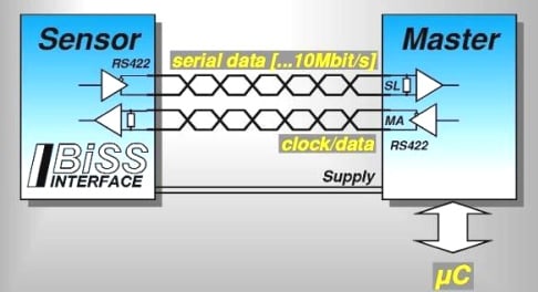
Fig. 8: BiSS interface data transmission with two unidirectional terminated RS485 lines plus power supply
DRIVE-CLIQ®
DRIVE-CLiQ, the Siemens standard digital interface between the essential SINAMIC S120 drive components including motors and encoders reduces the number of different parts. Electronic type plates in the components allow all of the drive components to be automatically detected via the Drive-CLiQ cable.
It is used to connect a motion controller with several servo drives and also to connect the drives with the motor build in feedback device. It is a non standardized closed system based on fast (100 MBit) Ethernet with a 24 V feedback power supply extension. Fastest position update rate is 31.25 µs. Electronic type plate functionality is available. Analog signals are not supported. Until now Siemens is not interested in opening the DRIVE CLiQ interface specification to third party industrial controls or motor manufacturers.
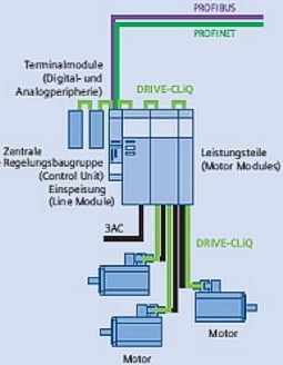
Fig. 9: SINAMIC S120 with DRIVE-CLiQ {7}
EnDat®
The EnDat interface from HEIDENHAIN is a digital, bidirectional interface for encoders. It is capable both of transmitting position values from incremental and absolute encoders as well as transmitting or updating information stored in the encoder, or saving new information. EnDat is based on one unidirectional RS485 clock channel and one bidirectional data channel. The data is transmitted in synchronism with the clock signal from the subsequent electronics. The type of transmission (position values, parameters, diagnostics, etc.) is selected by mode commands that the subsequent electronics send to the encoder.
EnDat version 2.1 supports clock rates up to 1 MHz and no cable length compensation. EnDat version 2.2 supports clock rates up to 16 MHz with cable length compensation.
In high performance servo drives EnDat 2.1 is always used in combination with analog sine and cosine signals. The digital channel is used for type plate data, commutation information and multi turn data.
With EnDat 2.2 the use of the analog signals is not necessary due to the much faster communication. That saves several wires of the feedback cable. The fastest position update rate is below 18 µs.
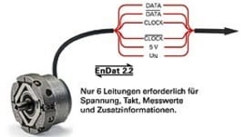
Figure 10: EnDat 2.2 required only 6 wires {8}
EnDat 2.2 FPGA sample code download for the EBV Electronic development board (Altera Quartus II VHDL) is available {5, 6}.
MAZeT is also offering a commercial soft-macro (IP) of the EnDat 2.2 interface. It describes the control side part (also referred to as the master component) of the interface between an absolute position encoder from HEIDENHAIN and a user’s subsequent electronics {9}.
HIPERFACE®
Is the short for High Performance Interface and the standard interface for SICK-STEGMANN motor feedback systems.
This interface was also developed for the requirements of digital drive control and offers the user a standardized and simplified electrical interface.
HIPERFACE® defines the standardized electrical interface with 8 wires:
- 2x supply voltage 7 … 12 V
- 4x analog incremental, differentially transmitted, sine/cosine signals
- 2x digital, bidirectional RS485 interface
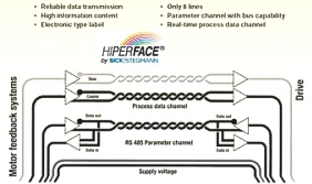
Fig 11: HIPERFACE still uses analog signals {10}
A fully screened 8TP cable securely transmits the signals to the controller. The protocol is handled with a standard (RS232) UART, as implemented on almost all popular microcontrollers/DSPs. The interface is configured to 9600 baud, as standard. Each protocol is completed with an easy to calculate XOR checksum. The end of the protocol is detected using a timeout control.
A full digital SICK-STEGMANN interface is under development. HIPERFACE DSL is planned to be available in two interface versions:
- A RS485 version with separate logic power and signal wires
- A DSL version with power and signals using the same wires
Detailed technical data is not published until now. HIPERFACE DSL is planned to be available in 2008.
Conclusion
This paper describes methods to interface high resolution encoders with a drive using FPGA and microcontroller technology.
There is no microcontroller on the market which can support industrial digital encoder interfaces. No drive Manufacturer is willing to use several dedicated integrated circuits to interface different encoders. Siemens for example supports only their company internal DRIVE CLiQ. However BiSS and EnDat can be easily implemented in a standard FPGA with RS485 drivers {5}. HIPERFACE DSL is probably also a candidate for an FPGA solution using the same hardware.
Real high performance (direct drive) applications can take advantage of an FPGA integrated observer based encoder interface solution with flash ADC, Oversampling and on-line offset / error correction.
Editors
Prof. Dr.-Ing. Jens Onno Krah
Fachhochschule Köln
Fakultät IME – NT
Heiko Schmirgel
Kollmorgen Europe GmbH
Düsseldorf
References
| 1. | Hengstler | www.Hengstler.com |
| 2. | S700 Manual | www.Kollmorgen.com |
| 3. | BiSS-Interface | www.biss-interface.de |
| 4. | IC-Haus | www.icHaus.de |
| 5. | Download | www.f07.fh-koeln.de/fakultaet/personen/professoren/jens.krah/ |
| 6. | EBV | www.ebv.com, www.devboards.de |
| 7. | Siemens | www.automation.siemens.com |
| 8. | Heidenhain | www.heidenhain.de |
| 9. | MAZeT | www.MAZeT.de |
| 10. | Sick-Stegmann | www.stegmann.de |
