


 Home >
 Knowledge Base >
 FAQs >
 Downloads >
Converting from a DS to a DSM Drive
This article refers to G&L PiC application note AN000035 and describes converting from a Centurion™ Line DS100 to a Centurion™ Line DSM100 and MicroDSM servo amplifiers from G&L.
Scope
This Application Note applies to the following G&L™ servo amplifiers:
- Centurion™ Line DSM100 and MicroDSM servo amplifiers from G&L
- Centurion™ Line DS100
Purpose
This Application Note provides information for applications converting from the DS series to the DSM series of servo amplifiers.
Body
The DSM servo amplifier can be used in all situations where a DS servo amplifier was used in the past. DSM servo amplifiers were designed with upgrade in mind. The servo amplifier and motor performance are the same as the DS servo amplifier if the same Gain parameters are used. The DSM servo amplifier supports all the different types of motors previously run by the DS servo amplifier.
Mechanically the foot print of the DS and DSM100 series servo amplifiers are the same. The DSM servo amplifier will bolt into the same place as the DS servo amplifier.
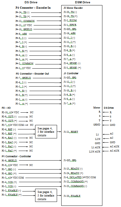
There are some things that are different about the DSM servo amplifier. The Electrical input connections on the DSM servo amplifier are 24 V source inputs. The DS servo amplifier used sinking inputs. Therefore, a relay may be required on the inputs listed below. See the Wiring Conversion Schematic for pin to pin connections.
Enable - Drive enable
RST - Drive reset
FAC - Forward current enable
RAC - Reverse current enable
Note: Normally the RAC and FAC inputs were always enabled to allow forward and reverse motor directions, therefore these inputs are no connects when converting to the DSM drive. If motor direction is to be inhibited then connect RAC or FAC to a selectable drive input in the same manner as connecting to the Enable and Reset inputs. The selectable drive input must also then be set up correctly in the DSM drive via the DSMPro software.
The cabling connecting these inputs is also different. The connectors on the DS servo amplifier were a Molex style of connector. The DSM servo amplifier uses a mini-D style of connector. Giddings and Lewis supplies a terminal strip converter for these connections. There are two connectors required:
J1 terminal strip converter P/N: M.1016.9545 (old P/N: 401-04051-00)
J2 terminal strip converter P/N: M.1016.9581 (old P/N: 401-04076-00)
The communication protocol also changed from the DS to the DSM software. DSMPro is a new software package and is required for servo amplifier setup. DSMPro is a windows program. A new cable is also required. The part numbers are
DSMPro Windows Software: M.1017.0586 (old P/N: 502-60036-00)
DSMPro Cable 10 ft. : M.1016.9514 (old P/N: 502-04020-10)
Changes to the communication protocol may also have an effect if using a PiC900 to communicate to a DS servo amplifier. In this event a new Application Specific Function Block has been created, M_DSMCOM, for communicating to the DSM servo amplifiers from a PiC900. It will be necessary to reprogram the software using the M_DSMCOM function. To obtain this new function order:
Motion ASFB Software P/N: 503-18955-00.
Note: the Motion ASFB’s are now included on the Applications CD with PiCPro v11.0 and later.
Note: If multi-drop communications are being used to communicate to multiple DS servo amplifiers it will be necessary to connect a separate serial port to the DSM servo amplifier unless all DS servo amplifiers are replaced with DSM servo amplifiers.
Please refer to the DS, MicroDSM or DSM servo amplifier installation manuals for additional information.
Centurion DS to DSM Drive Wiring Conversion
DSM Drive Input Circuit Examples
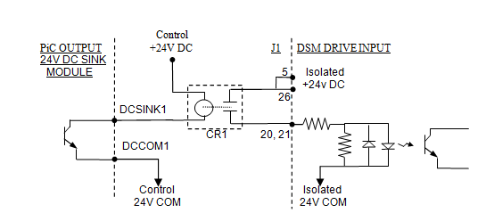
Enable or Reset Drive Input Connected to a Sinking Output Fig. 1
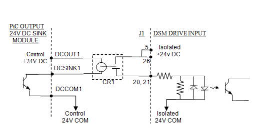
Enable or Reset Drive Input Connected to a Sinking Output Fig. 2
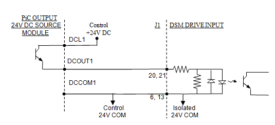
Enable or Reset Drive Input Connected to a Sourcing Output Fig. 3
DSM Drive Input Circuit Examples
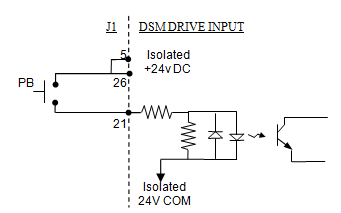
Reset Drive Input Connected to a Pushbutton Switch Fig. 1
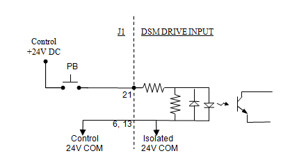
Reset Drive Input Connected to a Pushbutton Switch Fig. 2
Consult the DSM or MicroDSM servo amplifier installation manuals for additional drive input interface circuits.