Home >
 Knowledge Base >
 FAQs >
 Downloads >
AKD2G - Sending Secondary Feedback through EtherCAT
This article demonstrates Position Scaling for Additional Feedback Devices not used for Servo Control
Introduction
The AKD2G's various feedback options allow for incorporating up to 5 feedback devices into the drive. Occasionally the feedback is not used for servo AXIS control (a position used as a direct command or feedback to a servo axis) but used as an additional or axillary feedback signal for the motion/machine controller (PCMM, etc). The controller utilizes the position as a master or reference position. The attached application note covers the setup and scaling of this position that is sent through EtherCAT.
Feedback Screen
Additional Feedback Values
Two of the feedback values not used for direct AXIS control can have FBx.P scaled and sent through EtherCAT to the PxMM controller.
Raw Feedback
- Workbench Screen Name: Position
- AKD2G Parameter name: FBx.P
| Feedback Number | AKD2G Connector | Raw Feedback value reported in the Feedback screen in Workbench |
|---|---|---|
| 1 | X1 | FB1.P |
| 2 | X2 | FB2.P |
| 3 | X23 | FB3.P |
| 4 | X21 | FB4.P |
| 5 | X22 | FB5.P |
Position Format in Feedback screen
| n Pitches | Encoder Pitch |
|---|---|
| (64-FB#.BITS) bits | FB#.BITS bits |
Example
Encoder specs
- AKM2G motor connected to a slide (1 rev = 5mm)
- No Gearbox
- Feedback: Gurley SSI SSI Encoder
- Enc Resolution: 64 umeters/ line with 8 bit decode Analog to Digital Conversion
- Base resolution = 64 umeters/ line / 256 = 0.25 umeters
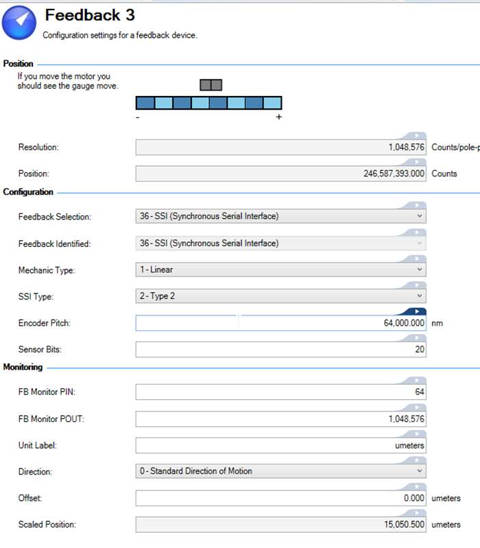
In WorkBench Feedback Screen set (shown in screen above):
- Sensor Bits = FB#.BITS = 20 note: Gurley signal into AKD2G X23 = 20 bits
- Encoder Pitch = FB#.LINEPITCH = 64000 nm (64 um)
Background
“FB#.P moves 2^20 counts per 64 um” is after the 12 bit shift left in the lower 32 bits.
- Gurley signal (Gcounts) coming into AKD2G X23 = 20 bits = 8 bit per line + 12 bits of lines
- Gurley line length = 64 umeters
- In the Gurley converter……… that leaves 12 bits (20 -8) for the total number of lines
- Making the total feedback range = 64 umeters x 2^12 = 262144 um
- Each line is decoded 8 bits (2^8) by the Gurley decode box
- 1 LSB (Gcount) of the Gurley encoder is 0.25 um
- That makes 64 um/line * 4 Gcounts/um= 256 Gcounts/line
- With the AKD2G scaling of 2^8 = 1 line then
- 1 mm move = 2^8 Gcounts x 1mm/0.064mm = 4000 Gcounts
- Then shift 12 bits left to conform to the AKD2G’s 32 bit format:
FB3.P = 4000 Gcounts*2^12 = 16,384,000 AKD2counts as reported by FB3.P on the WB feedback screen
EtherCAT Scaling

For Scaling the Feedback Position:
- AXIS1.CANOPEN.xxxx.xxx AKD2G parameters connect to 60Exh objects
- AXIS2.CANOPEN.xxxx.xxx AKD2G parameters connect to 68Exh objects
Additional Feedback 1:
| Object | FB1 to FB5 Subindex | Description | Associated AKD Parameter (x = Feedback number) |
|---|---|---|---|
| 60E8h | 1 to 5 | gearbox input revolutions (motor shaft revs) (Gear Ratio numerator) |
AXIS1.CANOPEN.GEARx.MOTORREVS |
| 60EDh | 1 to 5 | gearbox output shaft revolutions (driving shaft revs) (Gear Ratio denominator) |
AXIS1.CANOPEN.GEARx.SHAFTREVS |
| 60E9h | 1 to 5 | number of units per shaft rev (Feed Constant numerator) |
AXIS1.CANOPEN.FCx.FEED |
| 60EEh | 1 to 5 | number of shaft revs (Feed Constant denominator) |
AXIS1.CANOPEN.FCx.SHAFTREVS |
| 60E4h | 1 to 5 | Scaled Position sent through Ethercat (user Units) | N/A |
Additional Feedback 2:
| Object | FB1 to FB5 Subindex | Description | AKD Parameter* (x = FB number) |
|---|---|---|---|
| 68E8h | 1 to 5 | gearbox input revolutions (motor shaft revs) (Gear Ratio numerator) |
AXIS2.CANOPEN.GEARx.MOTORREVS |
| 68EDh | 1 to 5 | gearbox output shaft revolutions (driving shaft revs) (Gear Ratio denominator) |
AXIS2.CANOPEN.GEARx.SHAFTREVS |
| 68E9h | 1 to 5 | number of units per shaft rev (Feed Constant numerator) |
AXIS2.CANOPEN.FCx.FEED |
| 68EEh | 1 to 5 | number of shaft revs (Feed Constant denominator) |
AXIS2.CANOPEN.FCx.SHAFTREVS |
| 68E4h | 1 to 5 | Scaled Position sent through Ethercat (user Units) | N/A |
| Note | * Scaling parameters associated with an AXIS (not included in the Application note) have the additional designation “PRIMARY” in the name. Example: AXIS#.CANOPEN.FCPRIMARY.FEED |
EtherCAT COE Objects
EtherCAT uses DS402 COE objects to set the scaling. These objects and associated AKD2G parameters are different than the ones used for when the feedback is directly tied to the axis.
| COE Object | Description | AKD Parameter | Value |
|---|---|---|---|
| 60E8h Sub 1 | gearbox input revolutions (motor shaft revs) (Gear Ratio numerator) |
AXIS1.CANOPEN.GEARx.MOTORREVS | 1 |
| 60Edh Sub1 |
gearbox output shaft revolutions (driving shaft revs) (Gear Ratio denominator) |
AXIS1.CANOPEN.GEARx.SHAFTREVS | 1 |
| 60E9h Sub 1 |
number of units per shaft rev (Feed Constant numerator) |
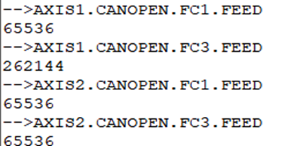
AXIS1.CANOPEN.FCx.FEED | 262144 |
| 60EEh Sub 1 |
number of shaft revs (Feed Constant denominator) |
AXIS1.CANOPEN.FCx.SHAFTREVS | 1 |
| 60E4h Sub1 |
Scaled Position sent through Ethercat (user Units) | N/A |
Calculations
- ECAT Position in uM = FB.P * (60E9 / 60EE) / (2^32 * (60E8 / 60ED))
- Factor out 1:1 gearing: FB.P * (60E9 / 60EE) / 2^32
- Convert FB.P into counts/line: FB.P * (2^(32-FB#.BITS) / 1) / 2^32
- Add in uM/line factor to get uM: FB.P * (2^(32-FB#.BITS) * uM/line) / 2^32
Solve with your settings: FB.P * (2^(32-20)*64) / 2^32 → FB.P * (2^12*64) / 2^32 → FB.P * 262144 / 2^32
- 60E9 (FC.FEED) = 2^(32-FB$#.BITS) * uM/line → 2^12 * 64 = 262144
- 60EE (FC.SHAFTREV) = 1
- 60E8 (GEAR.MOTORREV) = 1
- 60EE (GEAR.SHAFTREV) = 1
As shown in the AKD2G Workbench IDE:
WorkBench Units Scaling
(for use inside Workbench in Scope, terminal, and other screen)
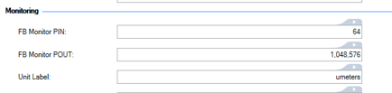
In the Feedback screen, the units the feedback number is displayed in (Scope, Service Mode, etc) can be set. The following example sets the units as umeters (micrometers)