Home >
 Knowledge Base >
 FAQs >
 Downloads >
AKD2G Actions Used for AC Mains Switch-Off after Controlled Stop
Overview
The controlled motion of any given axis of a machine will require the AC mains to be dropped after completion of an emergency-stop (NEC - Category 1). The necessary NEC stop category is determined based on the machine builder’s safety audit. This application note is only valid for Stop Category 1.
Dropping the AC mains, as well as other circuits, can provide the redundancies required for meeting certain safety ratings. A time-off relay is commonly used to allow for a time delay between starting a controlled stop function and dropping the STO, HW enable, and/or AC mains, etc.
This document outlines the setup in the AKD2G to use Actions with the command buffer feature with a time-delay to switch off the output relay (Digital Output 9) to drop AC mains power. This can eliminate the need for an external time-off relay.
Safety Audit Responsibility
This setup has no SIL rating in and of itself. However, it does provide some redundancy that can assist in meeting the necessary safety requirements defined by a safety audit. It is the responsibility of the machine builder to perform a safety audit and determine the necessary requirements for meeting specific safety ratings and regulations.
Function Description
When pressing an e-stop button, the drive will perform a controlled stop and then automatically switch off the AC mains contactor relay. Upon starting the controlled stop function, the drive also starts a time delay after which the drive’s relay output (DOUT9) is switched off. This output is used to control the switch-off of an AC mains contactor relay.
It is assumed that after the AC mains relay is opened, the relay will remain in the open position until it is reset manually or via a different signal from the machine interface. Switching the AC mains contactor relay back on (closed) is not performed by the drive.
Controlled Stop Configuration
The scope of this document does not include detailed explanations regarding controlled stop. The following contains some setup instructions, but the user should consult the help documentation and/or applications engineering to make sure the drive is configured properly to meet the necessary safety requirements based on the safety audit.
The setup for controlled stop should be based on an evaluation of the application. There are many things to consider for determining best practice.
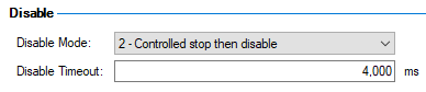
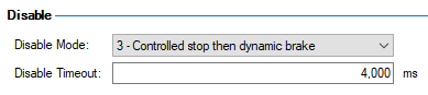
- Set the disable mode (AXIS#.DISMODE) to one of the following:
- 2 – Controlled stop then disable
- 3 – Controlled stop and then dynamic brake
- Note: See the help documentation on AXIS#.DISMODE and “Controlled Stop” for detailed explanations.
- Set the controlled stop disable timeout (AXIS#.DISTO) to a length of time that allows motion to come to a complete stop. This depends on the controlled stop deceleration rate (AXIS#.CS.DEC).
- Set the controlled stop parameters appropriately for the machine.
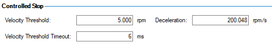
If AXIS#.DISTO or AIXS#.CD.DEC are set too low or if the motor is running too fast, the controlled stop will not complete in the time specified by AXIS#.DISTO. The drive will generate the F6005 fault “Emergency timeout occurred”, and the power stage will disable immediately. The drive’s reaction to a fault is defined in the fault table.
Actions Configuration
(Controlled Stop with Time Delayed AC Mains Switch-Off)
An action can be configured to handle switching off the AC mains relay after a time delay. This is useful in combination with a controlled stop function to eliminate the need for an external timer relay.
It is the responsibility of the machine builder to perform a safety audit and determine the necessary requirements for meeting specific safety ratings and regulations.
Action 1: (controlled stop)
|
Task |
Controlled stop then disable |
|
Source |
Digital Input 1 |
|
Condition |
Inverted |
Note: The condition is “Inverted” so that the input wiring for the controlled stop will be fail safe. The controlled stop function will be commanded when the input goes low.
Action 2: (delays switching off DOUT9)
|
Task |
Command Buffer |
|
Source |
Digital Input 1 |
|
Condition |
Falling Edge |
|
Buffer |
DRV.CMDDELAY 2000; DOUT9.STATEU 0 |
Note: The time delay in milliseconds must be long enough for the controlled stop to complete.
Note: The operator must wait for Action 2 to complete before switching Input 1 back on. Another digital output can be used in the command buffer to provide indication that the action is complete.
Action 3: (switch on DOUT9 to recover from controlled stop and on boot up)
|
Task |
Command Buffer |
|
Source |
Digital Input 1 |
|
Condition |
Rising Edge (Triggers on High at Start) |
|
Buffer |
DOUT9.STATEU 1 |
Note: “Triggers on high as start” means that if the input is high when the drive boots up, the action will be executed.
Action 4: (clear faults, delay, and enable)
|
Task |
Command Buffer |
|
Source |
Digital Input 2 |
|
Condition |
Rising Edge |
|
Buffer |
AXIS1.CLRFAULTS; DRV.CMDDELAY 1000; AXIS1.EN |
Note: These commands can be handled by separate actions or through other communication with the drive.
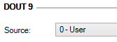
Output 9 Configuration
In this case, the source for digital output 9 must be configured for “User”, so the command buffer can control the output via the DOUT9.STATEU parameter.
Example of Required Relay Type
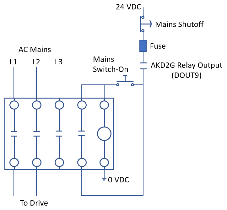
This is only an example to show the general type of contactor with 24VDC coil and a N.O. auxiliary contact. The mains relay must be sized appropriately for the current and voltage ratings of the drive.
AC mains contactor relay: WEG Electric CWB9-11-30C03
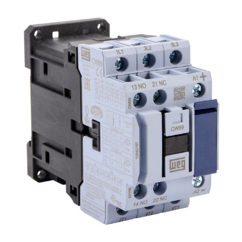
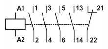
Three N.O. power contacts, 24 VDC coil voltage. (1) N.O./(1) N.C. auxiliary contacts included.
- Terminals A1/A2 = coil
- Terminals 1/2, 3/4, 5/6 = AC mains
- Terminals 13/14 = used for the hold circuit
Example Wiring Diagram