Eliminating electromagnetic interference (EMI) noise in motor and drive systems requires a layered approach. Shielded cables, common-mode chokes, proper cable routing, solid 360° shield connections and effective grounding all work together to reduce electromagnetic interference and improve system reliability. But no single technique eliminates EMI on its own, and not every system experiences EMI-related problems. The key is understanding where EMI originates, how it travels through a system, and where mitigation techniques have the greatest impact.
Key takeaways
- Reducing EMI requires a system-level approach. Cable design, routing, shielding, grounding and filtering work together to minimize electromagnetic interference.
- Purpose-designed cables, proper cable separation and common-mode chokes help prevent electrical noise from affecting motors, drives and feedback devices.
- Proper grounding and 360° shield terminations are essential for effective EMI mitigation. Without a low-impedance grounding path, even well-shielded cables cannot provide reliable electromagnetic compatibility (EMC).
What causes EMI noise in electric motors and drives?
EMI noise originates from the high-frequency switching currents inherent to drive operation. Every electromagnetic circuit generates some level of EMI noise, and without mitigation it can disrupt sensitive feedback devices, controls and nearby electronics.
That's because cables that have been poorly designed or improperly installed can act as antennas that transmit EMI and cause components to malfunction. The result can be unplanned downtime, loss of productivity or even hazardous operating conditions. The most effective way to prevent these outcomes is to identify the source of EMI noise early, and apply targeted EMI shielding techniques at the cable, drive and cabinet level.
How does cable design reduce EMI noise?
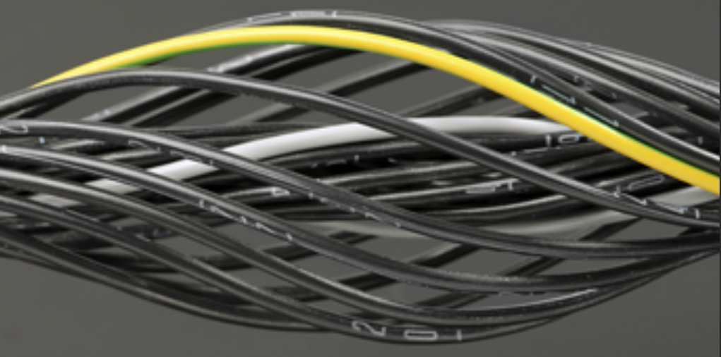
Well-designed cables are the single most impactful tool for EMI noise reduction in servo systems. The wire gauge, outer casing material, flex ratings, termination quality and shielding all contribute to minimizing noise issues. Kollmorgen engineers have found that systems using purpose-designed motor and feedback cables experience significantly fewer EMI issues than systems assembled from generic or field-built cables.
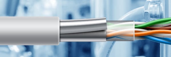
While the minimum shield coverage recommended for Kollmorgen motor and drive systems is 85%, Kollmorgen cables are rated at 90% coverage. For applications combining motor power and feedback in a single cable run, we also offer integrated motor/feedback cables engineered with shielding needed to mitigate noise between the motor power and feedback signals. This helps reduce overall cable costs while simplifying installation.
For a deeper look at the four key specifications that determine cable performance—voltage, current, shielding, and flexibility—see Kollmorgen’s four key cable design considerations.
When should you use common-mode chokes on motor leads?
Common-mode chokes are required on motor power leads when cable runs exceed 25 m (82 ft). A common-mode choke is a filter component that blocks high-frequency noise common to two or more conductors while allowing the intended motor power signals to pass through. Without chokes on long motor leads, high-frequency switching currents from the drive can travel along the cable and radiate as EMI, degrading feedback device performance and triggering false or intermittent drive faults. Always consult your drive product documentation to confirm the specific choke requirements for your application, as drive amperage and cable length together determine the correct choke specification.
| Cable Length | Recommended Action |
|---|---|
| Under 25 m (82 ft) | Standard shielded cable; choke typically not required |
| 25 m (82 ft) or longer | Add motor common-mode choke on motor power leads |
How far should signal cables be separated from power cables?
Signal cables must be bundled and routed separately from motor and power cables to prevent EMI from transfering between them. Kollmorgen specifies the following minimum separation distances based on drive amperage:
| Drive Rating | Minimum Separation |
|---|---|
| <20 Amps | 100 mm (4 inches) |
| 40 Amps | 150 mm (6 inches) |
| 80 Amps | 200 mm (8 inches) |
If using a separate AC power filter, maintain separation of leads entering and exiting the line power filter. Locate the filter as close as possible to the point where the incoming power enters the cabinet.
If using a drive that contains an internal mains filter, maintain at least 100 mm (4") of separation between line power and motor leads. If input power and motor leads need to cross, cross them at 90 degrees.
How should cables be spliced and shielded to prevent EMI?
Proper splicing and shielding technique are essential for maintaining continuous EMI noise reduction along the full cable run. When cables must be divided, use connectors with metal backshells and ensure both shells connect along the full 360°of the shields. No portion of the cable should be left unshielded at any point in the run. Never divide a cable across a terminal strip, because doing so breaks shield continuity and creates an EMI radiation point.
For cables entering a control cabinet, connect shields on all 360°of the cable. Avoid connecting the shield to ground through a short wire lead, where only a small portion of the shield braid is connected to is grounded, as this significantly reduces shielding effectiveness. Instead, use a full 360° clamp in direct contact with the shield and connected to the grounding plate.
How do differential inputs and internal filtering reduce electrical noise?
Using differential inputs for analog signals greatly reduces noise susceptibility on signal cables. The ideal wiring approach is to connect the output signal to the plus (+) differential input and the ground of the output-generating device to the negative (–) differential input. Signal cables used in differential input configurations should be twisted-pair, shielded signal lines, and connect shields to grounds on both ends. Many Kollmorgen drives provide internal signal filtering to further reduce the effects of electrical noise on analog signals—an added layer of EMI noise reduction that requires no additional hardware.
What grounding practices are required to eliminate EMI noise?
Grounding quality determines whether shielding and filtering actually work. For cabinet components, connect the back panel and cabinet door to the cabinet body with several conductive braids. Never rely on hinges or mounting bolts for ground connections. You also want to provide an electrical connection across the entire back surface of the drive panel. Electrically conductive panels, such as aluminum or galvanized steel, are preferred. But for painted or coated metal panels, remove all coating behind the drive mounting area before installation.
The cabinet must connect to a proper earth ground, and ground leads should be the same gauge—or one smaller—as the leads to mains power.
One critical distinction is that high-frequency EMI grounding is not the same as a safety ground used to prevent fire or electrocution. High-frequency signals conduct on the skin of a wire, not through its core. Galvanized screws act as resistors, and paint or thin coatings between conductors behave more like capacitors than insulators. Any break in the low-impedance ground path forces EMI signals to radiate, defeating every other mitigation measure in the system.
The final link in EMI reduction
Electromagnetic interference is a predictable challenge in any motion system—and a solvable one. Reducing it requires a system-level approach that combines proper cable design, shielding, grounding, cable routing and filtering to interrupt the paths through which electrical noise travels. When these best practices are applied together, they support EMC compliance, protect sensitive electronics and prevent unplanned downtime.
Ready to reduce EMI noise? Consult a motion expert to review your installation and identify the most effective EMI mitigation plan of attack.
Frequently Asked Questions
What is the difference between EMI and EMC in motor systems?
EMI (electromagnetic interference) is the unwanted noise energy that can disrupt electronics. EMC (electromagnetic compatibility) is the broader requirement that equipment both limits the EMI it emits and continues to operate properly in the presence of a specified level of external interference. In practice, EMC is the goal, and EMI control is the work you do to achieve it.
How do I know if EMI noise is the cause of my drive faults or unexpected motor motion?
Common symptoms of EMI in servo systems include unexpected motor movement, failure to stop on position, intermittent drive faults related to feedback or current loop errors, and issues on one axis triggered by cable problems on a separate axis. To isolate the source, disconnect all cables but the suspected axis, verify normal operation, then reconnect remaining cables one at a time until the fault reappears. Kollmorgen motion experts recommend first inspecting shield connections, grounding plate continuity and cable separation.
Can I use a single cable for both motor power and feedback without creating EMI noise issues?
Yes, provided the cable is specifically designed for combined motor power and feedback use. Kollmorgen offers single motor/feedback cables engineered with appropriate shielding to mitigate noise issues between power and signal conductors. Generic or field-assembled cables that combine power and feedback without purpose-built shielding will typically introduce EMI noise into the feedback path, leading to degraded system performance or instability.