Home >
 Knowledge Base >
 FAQs >
 Downloads >
Using AKD Capture Engine with KAS - PLCopen Motion Engine
The following pertains to applications using the KAS PxMM controller with AKD drives. It contains relevant information you may need to know when setting up position capture with the PLCopen motion engine
KAS can use 1 or both capture engines inside the AKD drive to full fill the needs of an application. There is information on this in the KAS IDE manual. To access the information do a word search on capture.
Key concepts to remember when setting up the position capture with PLCopen Motion:
- Transfer of information through EtherCAT. The KAS Controller communicates to the AKD drive via EtherCAT including setting up, arming, trigger status and latch information (position or time)
- Trig.Ref Function. This function is used as an input(called Trigger Input) to several PLCopen motion function blocks(MC_TouchProbe,MC_Reference, MC_MachRegist, MC_MarkRegist) that make use of the AKD's capture engines. The Function has 4 elements explained here:
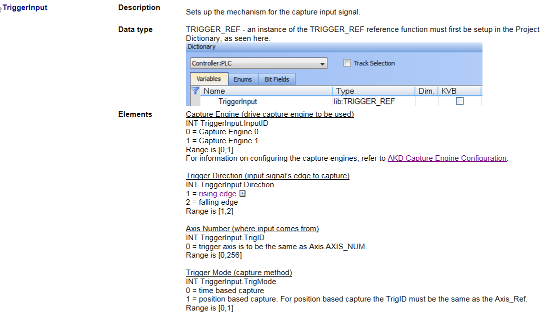
The Trigger input defines which one of the 2 AKD capture engines to use, which signal edge to capture, Axis number for the trigger input, and the trigger mode (position, time , etc). When a Function block with a Trigger Input is called in a KAS program it will override any present settings
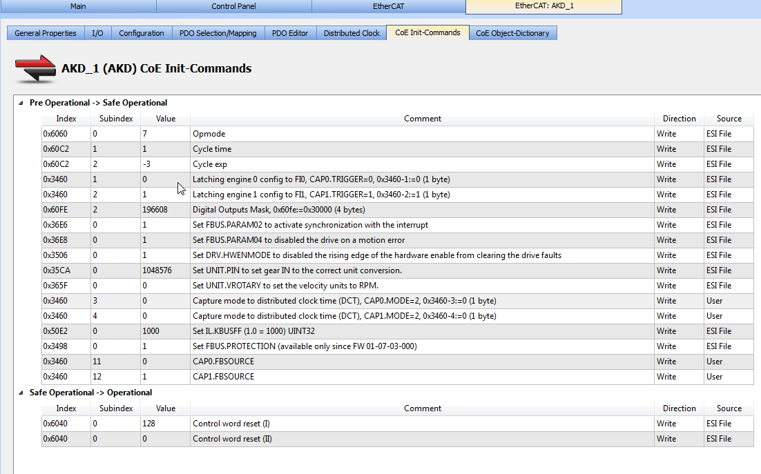
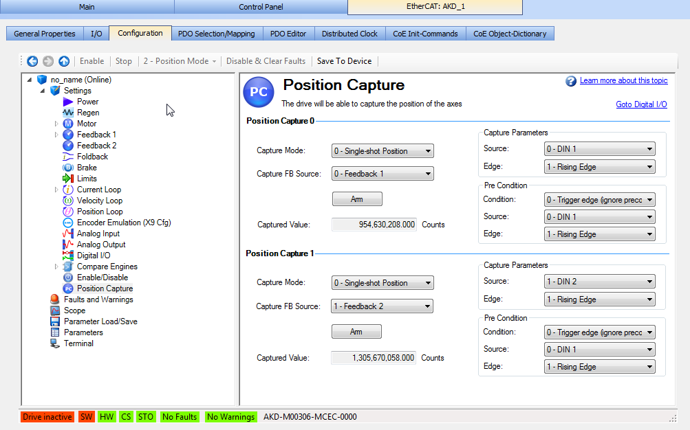
- COE Init functionality: When a project is started in KAS and the EtherCAT network is initialized, The controller will set the parameters located in the COE Init tab for the axis:
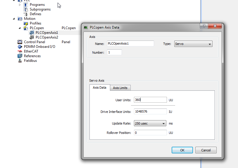
- Units in the Application (UU or User Units) and Workbench units. These units can be different as each is setup in a separate place. UU are set up in the KAS project in Motion/ PLCOpen / PLCOpenAxis1. Therefore the values may be different but the system capture could be working correctly
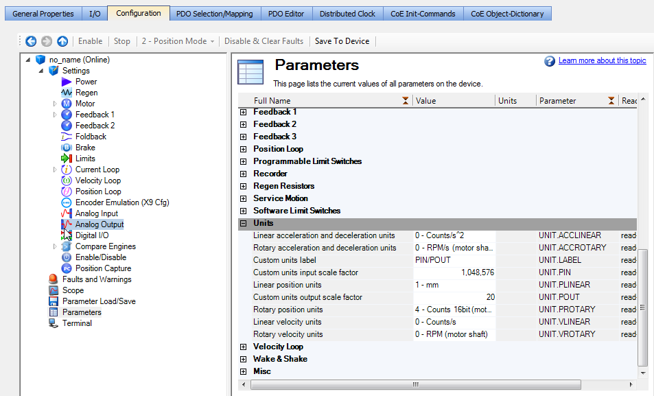
And Workbench units for drive setup are setup in the Parameter screen Embedded in the IDE when in the IDE On-Line Configuration or Run Mode is active.
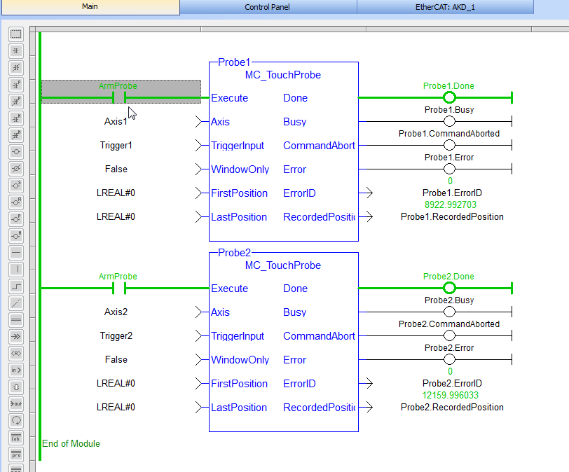
Here is a example of different units as shown in the Captured Position Value. KAS Controller units setup for 1000 UU/rev and Workbench units set up for feedback counts/rev
Attached is a cross reference guide showing the various setup and status parameters and how they are named in the control, in the COE communications , and in the drive side parameters and if accessible in the WorkBench Capture screen.