


 Home >
 Knowledge Base >
 FAQs >
 Downloads >
S700 Safety: Safely limited speed
General
The following documents are important for an understanding:
- Operating instructions "PNOZ m1p" and "PNOZ mo1p" (download area of the international Internet site of Pilz www.pilz.com)
- Instructions Manual S701...724
- Operating instructions for Safety Card S2
Products used:
- PNOZ m1p (Pilz)
- PNOZ mo1p (Pilz)
- S700-S2 (Kollmorgen)
- AKM Motor (Kollmorgen)
- Motor cable, 5 m (Kollmorgen)
- Feedback cable (Hiperface) 5 m (Kollmorgen)
- PNOZmulti Configurator (Pilz)
- SafetyGUI (Kollmorgen)
Example Application
The example shows the implementation of the operating mode "Configuration – Safely limited speed upon activating a confirmation switch" with a mode selector switch, a confirmation switch, a PNOZmulti and an S700 with built-in S2 safety card.
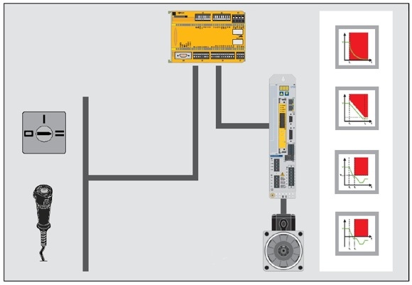
The safe control and analysis of the signals is performed by the function modules
![]() Mode selector switch,
Mode selector switch, Confirmation switch and
  Emergency stop
from the element selection (input elements).
Mode selector switch function
A mode selector switch (S6) on a machine with 2 positions for the operating modes Automatic and Setup is to be monitored by PNOZmulti. The automatic continuous running is not dealt with in any detail in this example. These considerations are listed only for the setup mode with confirmation function (SS2, SLS, SDI), other operating modes and safety functions must be considered separately.
The FS function module (FM) mode selector switch is assigned to the operating mode inputs in the application program. The FM monitors the time of the switching operation and does not detect plausible operating modes, such as no operating mode selected (all inputs of the mode selector switch are 0). If an error occurs, the enable output of the FM is immediately reset. The enable output is also reset for a STOP of the PNOZmulti and when switching on the PNOZmulti. The signal at the enable output must be analysed by the application program and lead to a corresponding response.
Based on an entry in the error stack, it can be determined why the enable output has been reset.
The acknowledgment of the error is dependent on the type of the occurring error.
- No input features a 1-signal:
Establishing a permissible input signal at the inputs of the FM. - More than one input features a 1-signal:
Establishing a permissible input signal at the inputs of the FM and restart of the PNOZmulti.
By selecting the OM Setup and activating the start button (S4) with activated confirmation switch (S5), the drive is set into motion.
In setup mode, the safety functions SLS (safely limited speed) and SDI (negative or positive) safe direction of rotation monitoring are also activated. Direction and speed of the monitored axis are selected in such a way that the worker can always withdraw from the motion causing the danger.
If the function SLS or SDI or their configured limits are violated, the drive switches to STO.
It should be noted here that a holding torque is no longer available with STO and corresponding additional measures must be taken to ensure that this behaviour does not lead to a dangerous situation (e.g. with suspended loads).
Mode selector switch safety considerations
- A short circuit between 24 VDC and an input with non-selected operating mode is recognized as an error by the standard function module.
- A short circuit between 24 VDC and an input with selected operating mode is recognized as an error by the standard function module after the next switching operation.
Confirmation switch function
In this example, the PNOZmulti monitors the dual-channel three-level confirmation switch S5, which is equipped with two NO contacts and two positively driven NC contacts.
The Off function with automatic disconnection at level 3 of the confirmation switch is assigned to the "Emergency Off" FS function module in the application program. The FM detects if the Off function has been activated, but also incorrect input signals, such as exceeding the contact synchronization time.
The confirmation function of the confirmation switch is assigned to the "Confirmation switch" FS function module in the application program. The FM detects if the confirmation switch has been activated, but also incorrect input signals, such as exceeding the contact synchronization time.
If the confirmation switch is pushed through (EMERGENCY OFF) or an error occurs, the enable output of the FM is immediately reset.
This example requires a confirmation switch with a safety feature that prevents the confirmation function at level 2 from taking effect during a reset from level 3 to level 1. This is a prerequisite for the present application.
The signal at the enable output can be analyzed by the application program and lead to a corresponding response.
The acknowledgment of the error is dependent on the operating mode set at the FM.
The function modules Emergency Off and confirmation Switch are parameterised in this application example in such a way that no acknowledgment has to occur
- during restart (PSS switched on/off),
- during startup (STOP-RUN transition of PNOZ),
- after releasing the confirmation switch, or
- after pressing the confirmation switch
so that the enable output can be set again.
The signal of the enable output activates the function SS2 of the safety card with a falling edge at input SS2 of the safety card. If the configured limits of the SS2 function are violated, the drive switches to STO.
It should be noted here that a holding torque is no longer available with STO and corresponding additional measures must be taken to ensure that this behavior does not lead to a dangerous situation (e.g. with suspended loads).
Confirmation switch safety considerations
- Bridging a contact in the NO or NC contact circuit of the confirmation switch is detected by the FM during the next switching operation.
- A cross circuit between the input circuits of the confirmation switch is detected as an error by the PNOZ.
- A short circuit between 24 VDC and an input circuit of the confirmation switch is recognized as an error by the PNOZ.
- When the confirmation switch is returned from level 3 to level 1, the confirmation function is suppressed by the confirmation switch.
- The confirmation switch by itself must not be able to initiate any commands that lead to conditions resulting in any danger.
Wiring of the safety card
PNOZ Multi configuration:
The activation of the respective safety functions is performed via a falling edge at the inputs of the safety card.
Start:
The safe setup operation, in which the safely limited speed and direction of rotation are monitored, can be started if:
- the Setup operating mode has been selected, and
- the safety card is operational, and
- the confirmation switch has been activated, and
- the Start button has been pushed (the motion is triggered only with the Start button).
PNOZmulti outputs:
SS1 Activate : Safe Stop 1
SS2 Activate : Safe Stop 2
SLS Activate : Safely Limited Speed
SDI Neg Activate : Safely turning CCW direction
SDI Pos Activate : Safely turning CW direction
Reset : To reset the safety card after an error
To operate the safety card, it is mandatory that the signals SS1 and Reset are applied. These two inputs initiate a reset of the safety card. The Reset button at the PNOZmulti initiates the required signal sequence for the reset at SS1 and Reset of the safety card.
Remove the error and observe
- the error messages in the error stack
- the LED display.
1. Switch the two inputs SS1 Activate and Reset to 0 V.
- The safety card executes the SS1 (Safe Stop 1) safety function and changes to the "STOP" state.
The "FAULT" LED flashes.
2. Switch the two inputs SS1 Activate and Reset to 24 V.
- The safety card changes to the "STARTUP" state. The device and the safe pulse inhibitor are tested.
The "RUN" LED flashes. - The safety card changes to the "RUN" state.
The 'RUN' LED is permanently lit.
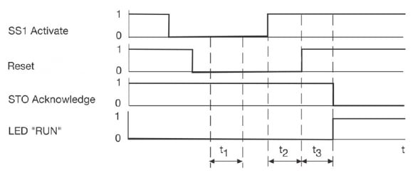
- t1 : at least 2 ms time while SS1 Activate and Reset have to have a "0" signal
- t2 : switching interval SS1 Activate – Reset
- t3 : approx. 2 s startup time of safety card
- SS1 Activate : input for safety function SS1
- Reset : input for SIL3 and Reset
- STO Acknowledge : output for acknowledgment signal of safety function STO
- "RUN" LED : system is operational
The remaining number of outputs is dependent on the number of safety functions configured on the safety card.
PNOZmulti inputs:
Reset : Initiates a reset of the safety card.
Start : Triggers the motion in the setup mode.
Ready : Reads the operational readiness of the safety card.
STO_ACK : STO activated.
Inputs for initiating the safety functions:
Application-dependent.
Motion Control safety considerations
- No dangerous situations may occur from braking ramps of SS1/SS2 and overtravel times.
- A perfect mechanism at the drive (over dimensioning) is assumed (exclusion of errors for a shaft break).
- The operator must ensure that the function of the safe pulse inhibitor is tested periodically by triggering the safety functions SS1 or STO, after 8 hours at the latest:
- with an operational restart after triggering the safety function SS1 or STO
or
- with a restart after triggering the safety function SS1 by the operator (see operating instructions).
Total application safety considerations
- The PNOZmulti and the combination of S700 / S2 safety card must be installed in the same installation space to rule out a short circuit between 24 VDC and a safety input of the card.
- An error in the PNOZmulti Mini or the combination of S700 / S2 safety card does not lead to a loss of the safety function.
Safety characteristic data
| Safety function according to EN ISO 13849-1 Safety-related control function (SRCF) according to EN 62061 |
Performance Level according to EN ISO 13849/1 |
Safety integrity level according to EN 62061 |
Safety-based parts of the control |
|---|---|---|---|
| Confirmation function – Releasing or depressing the confirmation switch stops the dangerous movement with Safe Stop 2 (SS2) (listed here only for manual operation; other OM must be considered separately) |
PL d | SIL 2 | Sensor (confirmation switch) Sensor (mode selector switch) Input (PNOZ m1p) Input (PNOZ m1p) Logic (PNOZ m1p) Output (PNOZ m1p) Actuator (safety card S2) |
| Safely limited speed (SLS) (listed here only for manual operation; other OM must be considered separately) | PL d | SIL 2 | Sensor (mode selector switch) Input (PNOZ m1p) Input (PNOZ m1p) Logic (PNOZ m1p) Output (PNOZ m1p) Actuator (S2 safety card) |
| Safe direction of rotation (SDI) (listed here only for manual operation; other OM must be considered separately) | PL d | SIL 2 | Sensor (mode selector switch) Input (PNOZ m1p) Input (PNOZ m1p) Logic (PNOZ m1p) Output (PNOZ mo1p) Actuator (S2 safety card) |
Prerequisites:
| Description | Identification | |
|---|---|---|
| Failure due to a common cause (CCF): | Requirements are considered fulfilled, β=2% (must be checked during implementation) | |
| Service life | 20 years | |
| Activation interval (electromechanical components): | Sensor | 1 activation every 2 hours for confirmation switch (0.5 per hour) |
| Sensor | 1 activation per day for mode selector switch | |
| Confirmation switch: | B10d | 100.000 |
| Ratio of dangerous errors | 50 % | |
| Mode selector switch: | B10d | 100.000 |
| Ratio of dangerous errors | 50 % | |
Pease observe additional requirements of EN 62061 (e.g. requirements for systematic safety integrity) and EN ISO 13849-1 (e.g. requirements for avoiding systematic failures).
The calculation of the performance level is valid only with an AKM motor.
Circuit diagrams
PDF file, 7 pages
References
Pilz application document "1002086_DE_01": Safely limited speed at PMCprotego DS with PNOZm1p
Back to top