Home >
 Knowledge Base >
 FAQs >
 Downloads >
KAS T-Bot Motion Control
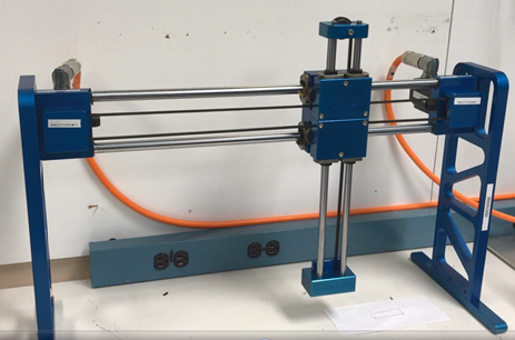
Table of Contents
Introduction
This application note details using the KAS PxMM multi-axis controller to control a 2 axis T-Bot mechanism. A T-Bot performs 2 axis control through a mechanism (a single belt with fixed pulleys that drives both axes). The T-Bot creates full motion within a 2-dimensional envelope. A KAS project file and a printable DOCX file are attached at the bottom of this article.
The application was created by first starting out with the following template:
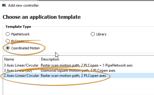
Code was then added and removed as needed to create the 2 axis T-Bot control.
Key Code That Was Added
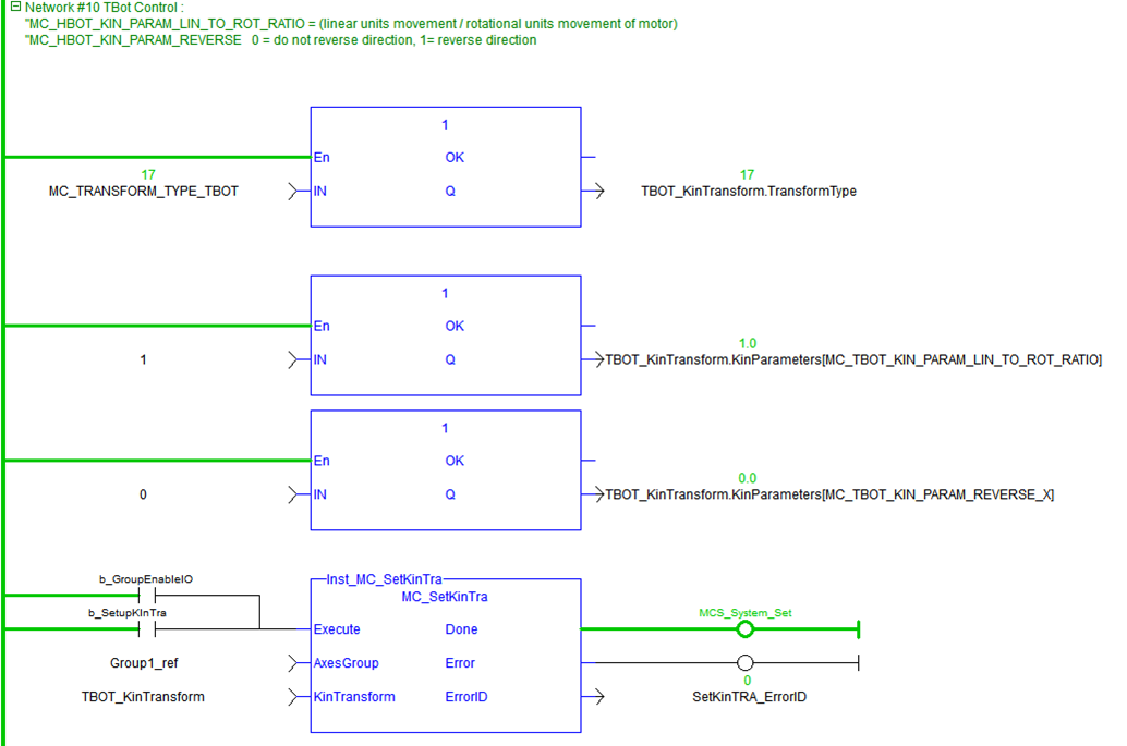
Setup MCS Coordinate system (added to the Main Program Step 6)
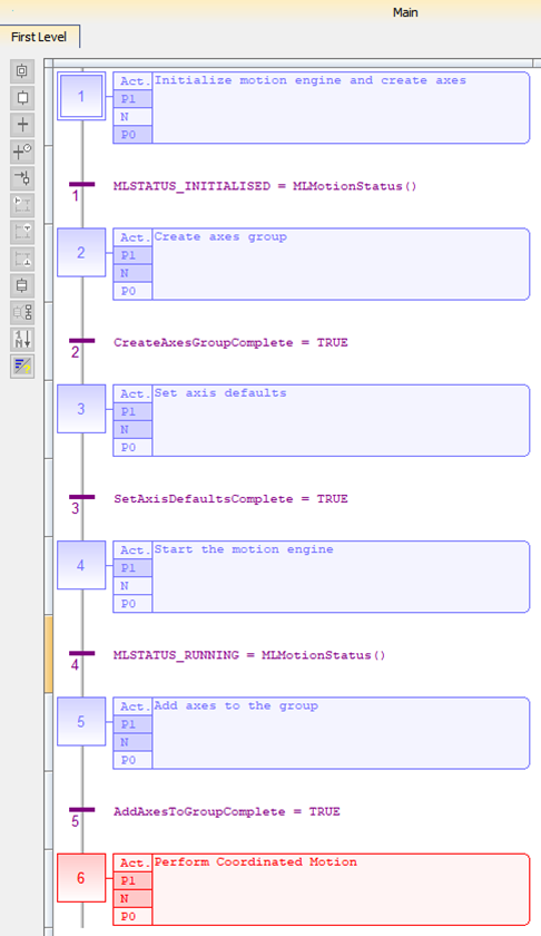
The T-Bot mechanism utilizes the MCS (Machine Coordinate System) as opposed to the ACS (Axis Coordinate System) that KAS usually employs. The MC_Kin_Ref Structure (see KAS help) defines the T-Bot robotic system transform and the Function MC_SetKinTra (see KAS help) initiates it:
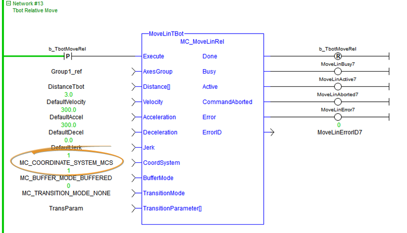
Relative and Absolute Motion
A relative and absolute move were also added to the Man Program. Note the Coordinate System input is set to 1 for the MC_COORDINATE_SYSTEM_MC. Here is the Function Block for the Relative Move:
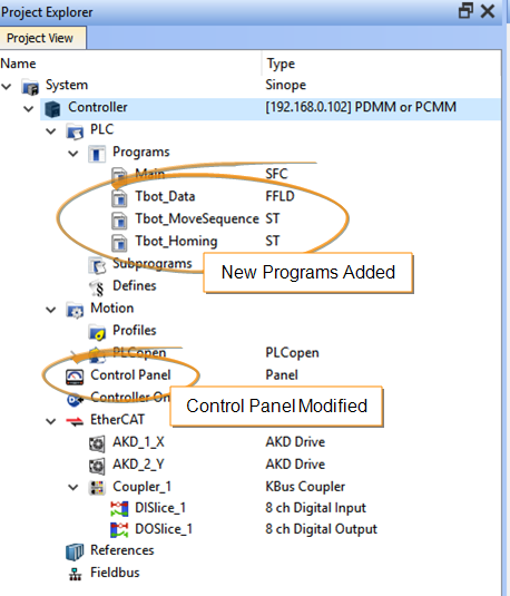
Homing the T-Bot
The program TBot_Homing was added to home the T-Bot. Homing consisted of moving to a hard stop (end of travel), first the X-axis (horizontal), then the Y-axis (vertical). Prior to homing, the max current of the X and Y axis was limited to maintain T-Bot mechanical integrity. The end of travel was sensed by the position error exceeding a preset value. After both axis physical limits are sensed an offset of 2 inches is made on each axis. At the end of homing the max currents are reset.
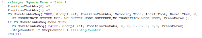
Motion Sequence (using Absolute and Circular interpolation)
A new program Tbot_MoveSequence was added that sequences motion through linear and circular interpolation moves.
Sample of the Linear interpolation move

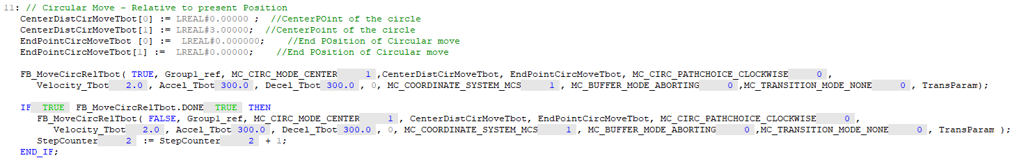
The circular interpolation move makes a complete circle:
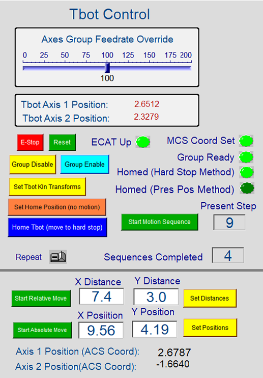
Control Panel
The Control Panel was modified to operate the T-Bot. The sequence to start motion is:
- Wait for “ECAT Up” LED to turn on after project starts running
- Click on “Group Enable”
- Click on “Set Tbot Kin Transform” button. “At completion, the MCS Coord Set” LED will turn on
- Click on “Home Tbot (Move to Hard Stop)”. At completion, the “Home Hard Stop Method” LED will turn on
- Click on “Start Motion Sequence” button or ether the “Start Absolute Move” button or “Start Relative Move” button to make one move per the Position/Distance inputs. After changing these inputs click the Yellow Set buttons for the new parameters to take effect.
Remote IO Control
An AKT-DNH-000 8 remote Input module and AKT-DT-000 8 remote output module were added to exercise the T-Bot demo from Remote IO.
- AKT-DNH-000 8 remote input module
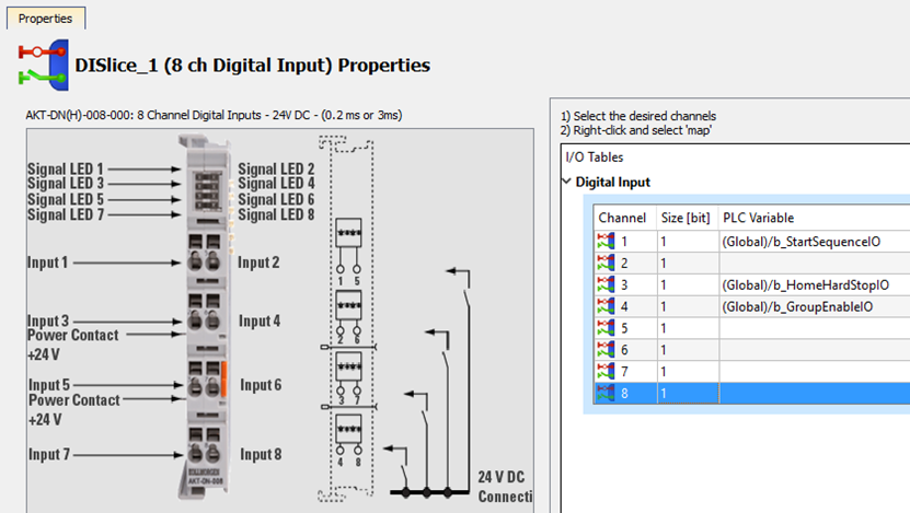
- b_GroupEnableIO – Enables drives and sets up T-Bot Kinetic transform
- b_HomeHardStopIO – Home axis and moves to start position
- b_StartSequenceIO - Execute Motion Sequence (will repeat sequence when this input remains high
- AKT-DT-000 8 remote output module
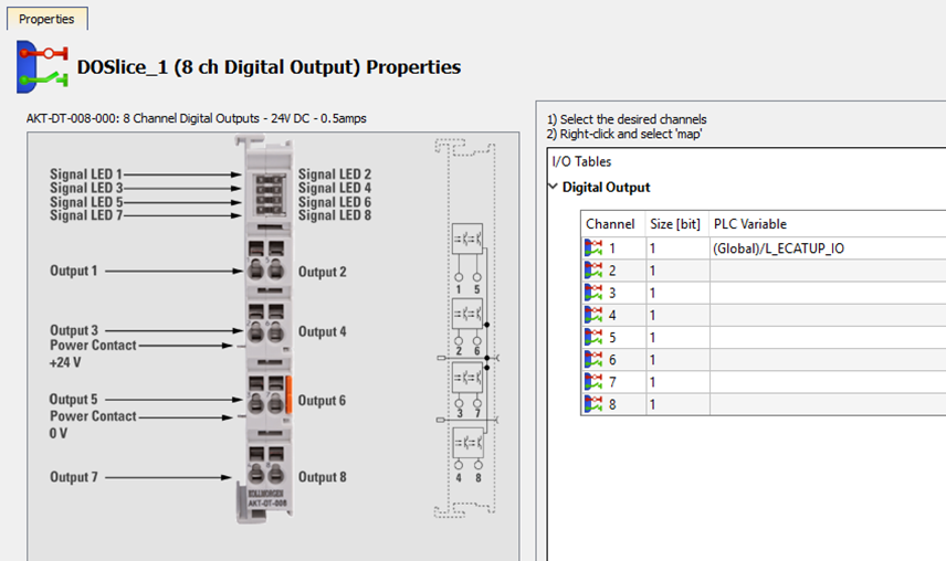
- b_StartSequenceIO – indicates when ECAT network is up and drives are ready to be enabled