


 Home >
 Knowledge Base >
 FAQs >
 Downloads >
Setup of Camming S400-S600
Table of Contents
- Activation of different cams with the ASCII command SWEx and SWExN
- Activation of different cams with the ASCII command SWCNFG
- ASCII command SWCNFG2
- Report of position messages via digital outputs
- Cam status request with the ASCII command DRVSTAT
- Logical connection of several cams to one digital output with the ASCII command O1MODE or O2MODE
- Application example
The servo amplifier offers 6 position registers SWE0...SWE5 for supervision of position values. The registers can be configured:
- SWE1...SWE4 with configuration parameters SWCNFG
- SWE0 and SWE5 with configuration parameters SWCNFG2
In addition to the position registers SWE0...SWE5 cam registers SWE0N...SWE5N are implemented. These registers are used only in case of activated cam function.
The cam function is activated with the cam bits (Bit 3/7/11/15 of SWCNFG and Bit 3/7 of SWCNFG2). With set cam bit a cam message is reported, if the current position is between SWEx and SWExN (x=0...5).
Polarity of the cam message can be defined with the polarity bit (Bit 1/5/9/13 of SWCNFG and Bit 1/5 of SWCNFG2).
Activation of different cams with the ASCII command SWEx and SWExN
Switch on and switch off limits for cams of the position register 0 are set with the commands SWE0 and SWE0N. With other registers the commands are SWE1 / SWE1N ... SWE5 / SWE5N.
Activation of different cams with the ASCII command SWCNFG
Configuration bits for SWE1...SWE4
SWE1
| Bit 0 | =0 | Position/Cam Register SWE1 not active |
| =1 | Position/Cam Register SWE1 active | |
| Bit 1 | =0 |
Message if position is exceeded (PFB > SWE1) |
| =1 |
Message if position falls short of (PFB < SWE1) |
|
| Bit 2 | Reserve | |
| Bit 3 | =1 | Cam function for SWE1/SWE1N |
SWE2
| Bit 4 | =0 | Position/Cam Register SWE2 not active |
| =1 | Position/Cam Register SWE2 active | |
| Bit 5 | =0 |
Message if position is exceeded (PFB > SWE2) |
| =1 |
Message if position falls short of (PFB < SWE2) |
|
| Bit 6 | Reserve | |
| Bit 7 | =1 | Cam function for SWE2/SWE2N |
SWE3
| Bit 8 | =0 | Position/Cam Register SWE3 not active |
| =1 | Position/Cam Register SWE3 active | |
| Bit 9 | =0 |
Message if position is exceeded (PFB > SWE3) |
| =1 |
Message if position falls short of (PFB < SWE3) |
|
| Bit 10 | Reserve | |
| Bit 11 | =1 | Cam function for SWE3/SWE3N |
SWE4
| Bit 12 | =0 | Position/Cam Register SWE4 not active |
| =1 | Position/Cam Register SWE4 active | |
| Bit 13 | =0 |
Message if position is exceeded (PFB > SWE4) |
| =1 |
Message if position falls short of (PFB < SWE4) |
|
| Bit 14 | Reserve | |
| Bit 15 | =1 | Cam function for SWE4/SWE4N |
ASCII command SWCNFG2
Configuration bits for SWE0 and SWE5
SWE0
| Bit 0 | =0 | Position/Cam Register SWE0 not active |
| =1 | Position/Cam Register SWE0 active | |
| Bit 1 | =0 |
Message if position is exceeded (PFB > SWE0) |
| =1 |
Message if position falls short of (PFB < SWE0) |
|
| Bit 2 | Reserve | |
| Bit 3 | =1 | Cam function for SWE0/SWE0N |
SWE5
| Bit 4 | =0 | Position/Cam Register SWE5 not active |
| =1 | Position/Cam Register SWE5 active | |
| Bit 5 | =0 |
Message if position is exceeded (PFB > SWE5) |
| =1 |
Message if position falls short of (PFB < SWE5) |
|
| Bit 6 | Reserve | |
| Bit 7 | =1 | Cam function for SWE5/SWE5N |
Report of position messages via digital outputs
I/O expansion card (not available with S400!)
If an I/O expansion card is installed, the position messages are reported via these outputs:
SWE0: Next-InPos X11B.4
SWE1: PosReg1 X11B.6
SWE2: PosReg2 X11B.7
SWE3: PosReg3 X11B.8
SWE4: PosReg4 X11B.9
SWE5: Reserve X11B.10
The functions "Next-InPos" and "SWE0 Message" use for output the same digital output X11B.4, that means they cannot be used at the same time.
Base PCB
If no I/O expansion card is available, the position messages can be evaluated with the digital outputs of the base PCB.
SWE0: OxMODE=28 x=1,2
SWE1: OxMODE=12 x=1,2
SWE2: OxMODE=13 x=1,2
SWE3: OxMODE=14 x=1,2
SWE4: OxMODE=15 x=1,2
SWE5: OxMODE=29 x=1,2
Cam status request with the ASCII command DRVSTAT
All position messages are buffered in a status register, independent from the digital output function. The messages can be read from the status register via the serial interface or CAN-/PROFIBUS interfaces.
SWE0: Bit 21 (0x00200000) of DRVSTAT
SWE1: Bit 22 (0x00400000) of DRVSTAT
SWE2: Bit 23 (0x00800000) of DRVSTAT
SWE3: Bit 24 (0x01000000) of DRVSTAT
SWE4: Bit 25 (0x02000000) of DRVSTAT
SWE5: Bit 27 (0x08000000) of DRVSTAT
Logical connection of several cams to one digital output with the ASCII command O1MODE or O2MODE
Function of the digital output OUT1 (OUT2) can be configured with the command O1MODE (O2MODE). When this parameter has been changed, the amplifier must be switched off and on again.
These funtions are possible:
| Mode | Function | Description |
| O1MODE=36 | OR Logic | Digital output 1 shows the result of an OR operation with the bit variable DRVSTAT and a bit mask out of auxiliary variable O1TRIG |
| O1MODE=37 | AND Logic | Digital output 1 shows the result of an AND operation with the bit variable DRVSTAT and a bit mask out of auxiliary variable O1TRIG |
Application example
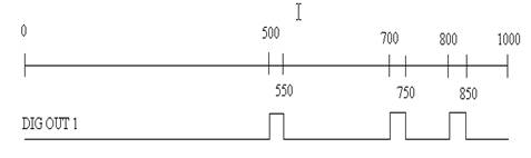
With a traverse from 0 to 1000 the digital ouput 1 should react as described:
The settings below can be done by using the terminal located in the setup software.
If this message appears during data input,
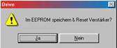
click NO.
|
ASCII Command
|
Description
|
|
DIS
|
Disable amplifier by software
|
|
SWE1 500
|
Cam start limit
|
|
SWE1N 550
|
Cam stop limit
|
|
SWE2 700
|
Cam start limit
|
|
SWE2N 750
|
Cam stop limit
|
|
SWE3 800
|
Cam start limit
|
|
SWE3N 850
|
Cam stop limit
|
|
SWCNFG 2457
|
Switch on register 1...3 with cam function, logic level not inverted
|
|
O1MODE 36
|
Switch on OR logic for register at digital input 1
|
|
O1TRIG 29360128
|
Define logic Bit 21...23 von DRVSTAT = 1
|
|
SAVE
|
Save parameter
|
|
COLDSTART
|
Activate new configuration
|
