


 Home >
 Knowledge Base >
 FAQs >
 Downloads >
Induction Machine - General
Table of Contents
Design
The drive of an three-phase asynchronous machine is done by a rotating field.
Rotor
- Squirrel-cage rotor: winding from solid conductor sticks (cage rotor) which are short-circuited. High currents flow through the leader sticks and produce strong magnetic fields together with the sheet irons.
- Slip ring rotor: rotor with wire windings whose ends are led to slip rings. These are connected by resistors during start-up and short-circuited gradually with an increasing speed. This rotor is employed at great performances to be able to limit the start-up current.
Stator
The stator consists of the case, the metal package and the inserted multi phase stator winding. Connection-pairs of the phase windings are usually led to a terminal board, where they are labeled with the classification letters U1 - U2, V1 - V2, W1 - W2.
Control
The motor speed can be controlled by servo amplifiers by increasing or reducing the frequency. This makes sense for installations which need a variable speed without an adjustable gearing having to be inserted.
Electrically the asynchronous machine corresponds to a transformer. The statorwinding is the primary side and the squirrel-cage rotor (cage) the secondary side. The current adapting depends on the speed. The rotor of the asynchronous machine always turns more slowly than the rotating field at the coils of the primary side (slip).
Start-up circuit
Servo amplifiers can start up smoothly and load adapted asynchronous machines in case of corresponding programming. Conventional startup circuits are not required.
Speed control
Different pole numbers and frequencies show the following speeds for the rotating field:
|
Pole number |
Pole pair number | nsync @ 50 Hz | nsync @ 60 Hz |
|---|---|---|---|
| 2 | 1 | 3000 rpm | 3600 rpm |
| 4 | 2 | 1500 rpm | 1800 rpm |
| 6 | 3 | 1000 rpm | 1200 rpm |
| 8 | 4 | 750 rpm | 900 rpm |
These are speeds of the stator rotating field, that means the speed which is inducted to the motor in the stator field windings in the stator by the mains. This speed also is described as a synchronous speed.
If the three-phase asynchronous machine is driven on a higher than the synchronous speed, it feeds performance back (generator mode) into the mains.
Frequency control
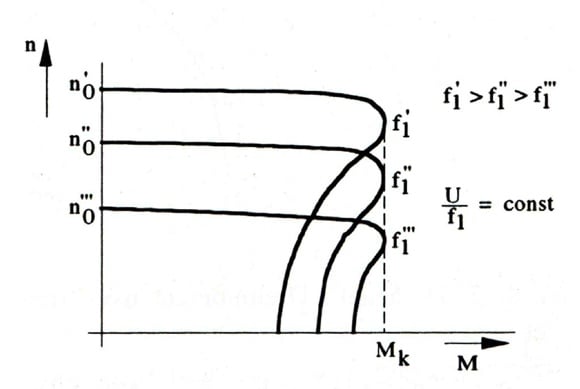
Speed/Torque curve
The characteristics in the picture represent the curves for the different frequencies of the stator tension. Squirrel-cage rotor engines with servo amplifiers are part of the most modern drives today
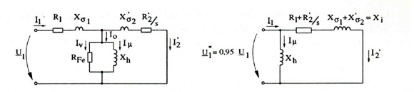
Substitute circuit diagram of an asynchronous machine a) complete (on the left) b)simplified (on the right)
By latest developments of the performance electronic devices, the power of these motors is increased further on.
Back to top