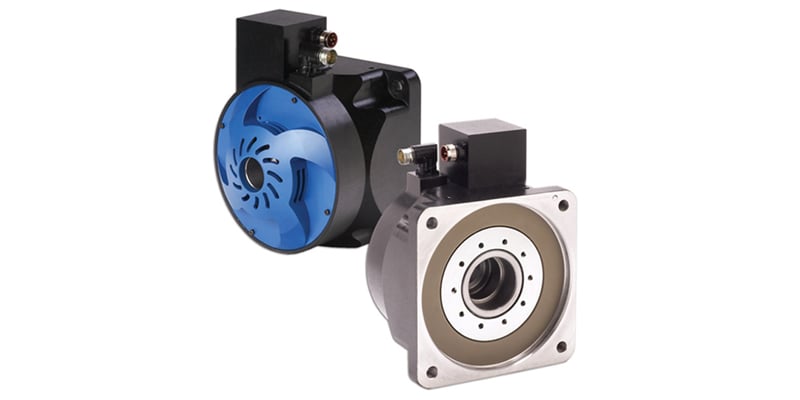
 A direct drive linear actuator, using a permanent magnet linear servo motor produces force and velocity based on the supplied current and voltage and provides a linear movement along the axis being driven. The linear servo motor works as part of a closed loop system providing force and velocity as commanded from a servo controller utilizing feedback to close the loop. In simple terms, a linear servo motor behaves identically as a rotary servo motor – it’s just rolled out flat and straight. Various feedback elements in the system supply information such as current, velocity, or position of the motor coil to the servo controller, which adjusts the motor action depending on the commanded parameters. A linear servo motor is a direct drive solution where the load is directly connected to the moving portion of the motor.

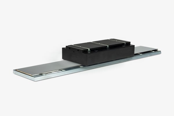
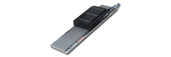
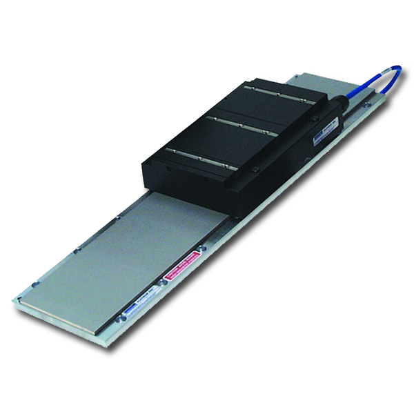
Direct drive linear motors are available in a variety of configurations (iron core, U-channel, tubular) but ultimately work the same. The direct drive linear actuator is part of a servo mechanism consisting of five key elements – a coil or forcer, a magnet way or magnetic shaft, a feedback device, mechanical elements consisting of linear bearings and supports, and driven by a servo drive or controller. The feedback device is typically a linear scale such as a linear encoder or transducer or can be other devices such as a potentiometer, Hall-effect device, tachometer, LVDT, or any other sensor as appropriate. The mechanical elements guide the forcer or coil along the magnet way, maintaining the proper air gap between the coil and magnets. Completing the servo system is the control electronics that powers the motor and compares the feedback data and command reference to verify that the linear servo motor is operating as commanded. There are many types of direct drive linear motor applications from simple X-Y stages to complex gantry systems - such as multi-axis laser cutting machines driven by complex motion controllers.
Similar to our blog on how a servo motor works, multiple embedded servo loops are tuned for optimal performance to provide precision motion control. The system consists of current, velocity, and position loops that utilize precision feedback elements. Each loop signals the subsequent loop and monitors the appropriate feedback elements to make real time corrections to match the commanded parameters.

The base loop is the current or force loop. Current is proportional to force in a linear servo motor, which provides acceleration or thrust. A current sensor is the device that provides feedback related to the current flowing through the motor. The sensor sends a signal back to the control electronics - typically an analog or digital signal proportional to the motor current. This signal is subtracted from the commanded signal. When the servo motor is at the commanded current, the loop will be satisfied until the current drops below the commanded current. The loop will then increase current until the commanded current is reached, with the cycle continuing at sub second update rates.
The velocity loop works in the same fashion with voltage proportional to velocity. The velocity loop sends the current loop a command to increase current (thus increasing voltage) when the velocity falls below the commanded velocity.
The position loop accepts a command from a PLC or motion controller which, in turn, provides a velocity command that is fed to the velocity loop which, in turn, commands the required current to accelerate, maintain, and decelerate the motor to move to the commanded position. All three loops work in optimized synchrony to provide smooth and precise control of the direct drive linear servo motor.