Home >
 Knowledge Base >
 FAQs >
 Downloads >
Functional Safety with AKD
Safety Comparison
| STO (Safe Torque Off) | SS1 (Safe Stop 1) |
 STO interrupts the power supply to the motor safely in the servo amplifier. The motor has no torque. STO interrupts the power supply to the motor safely in the servo amplifier. The motor has no torque. |
 The drive is stopped by controlled braking. Thereafter, the power supply for the motor is interrupted safely and the motor generates no torque. The drive is stopped by controlled braking. Thereafter, the power supply for the motor is interrupted safely and the motor generates no torque. |
| SS2 (Safe Stop 2) | SOS (Safe Operating Stop) |
 The drive is stopped by controlled braking and then remains at a controlled standstill. The control functions of the drive remain. The drive is stopped by controlled braking and then remains at a controlled standstill. The control functions of the drive remain. |
 Monitors the stop position reached and triggers for deviations above the prescribed limits SS1. The control functions for the drive remain active. Monitors the stop position reached and triggers for deviations above the prescribed limits SS1. The control functions for the drive remain active. |
| SDI (Safe Direction) | SSR1 (Safe Speed Range) |
 The SDI function ensures that the drive can only move in a defined direction. In case of error, SS1 is triggered. The SDI function ensures that the drive can only move in a defined direction. In case of error, SS1 is triggered. |
 Monitors the drive to maintain a defined speed range. In case of error SS1 is triggered. Monitors the drive to maintain a defined speed range. In case of error SS1 is triggered. |
| SLS (Safe Limited Speed) | SBC (Safe Brake Control), SBT |
 Monitors the drive to maintain a defined speed limit. In case of an error SS1 is triggered. Monitors the drive to maintain a defined speed limit. In case of an error SS1 is triggered. |
 Controls external brakes. SBT (Safe Brake Test) (not standardized): Test function for external and internal brake motor holding brake. Controls external brakes. SBT (Safe Brake Test) (not standardized): Test function for external and internal brake motor holding brake. |
| SLP (Safe Limited Position) | SLI (Safe Limited Increments) |
 Monitors the absolute position of the drive. If the predefined limit is reached, or if the brake torque is too small to stop the drive within the limit, SS1 is triggered. Monitors the absolute position of the drive. If the predefined limit is reached, or if the brake torque is too small to stop the drive within the limit, SS1 is triggered. |
 Monitors the relative position of the drive based on the current position when the function is triggered. SS1 is triggered when the specified limit is reached. Monitors the relative position of the drive based on the current position when the function is triggered. SS1 is triggered when the specified limit is reached. |
Stop
The stop function shuts down the machine in normal operation. The stop function is defined by IEC 60204.
Note: The Stop Category must be determined by a risk evaluation of the machine.
Stop function must have priority over assigned functions. The following stop categories are defined:
Stop Category 0
Shutdown by immediate switching off the energy supply to the drive machinery (this is an uncontrolled shutdown). With the approved safety function STO, the drive can be stopped using its internal electronics (IEC 61508 SIL2).
Stop Category 1
A controlled shutdown, whereby the energy supply to the drive machinery is maintained to perform the shutdown, and the energy is only interrupted when the shutdown had been completed.
Stop Category 2
A controlled shutdown whereby the energy supply to the drive machinery is maintained.
Stop Category 0 and Stop Category 1 stops must be operable independently of the operating moe, whereby a Category 0 stop must have priority.
IIf necessary, provision must be made for the connection of protective devices and lock-outs. If applicable, the stop function must signal its status to the control. logic. A reset of the stop function must not create a hazardous situation.
Emergency Stop
The Emergency Stop function is used for the fastest possible shutdown of the machine in a dangerous situation. The Emergency Stop function is defined by IEC 60204. Principles of emergency stop devices and functional aspects are defined in ISO 13850.
The Emergency Stop function will be triggered by the manual actions of a single person. It must by fully functional and available at all times. The user must understand instantly how to operate this mechanism (without consulting references or instructions.)
Note: The Stop Category for the Emergency Stop must be determined by a risk evaluation of the machine.
In addition to the requirements for the stop, the Emergency Stop must fulfill the following requirements:
- Emergency Stop must have priority over all the other functions and controls in all operating modes.
- The energy supply to any drive machinery that could cause dangerous situations must be switched off as fast as possible, without causing any further hazards (Stop Category 0) or must be controlled in such a way than any movement that causes danger is stopped as fast as possible (Stop Category 1).
- The reset must not initiate a restart.
Emergency Off
The Emergency Off function is used to switch off the electrical power supply of the machine. This is done to prevent users from any risk from electrical energy (for example electrical impact). Functional aspects for Emergency Off are defined in IEC 60364-5-53.
The Emergency Off function will be triggered by the manual actions of a single person.
Note: The result of a risk evaluation of the machine determines the necessity for an Emergency Off function.
Emergency Off is done by switching off the energy supply by electro-mechanical switching devices. This results in a category 0 stop. If this stop category is not possible in the application, then the Emergency Off function must be replaced by other measures (for example by protection against direct touching).
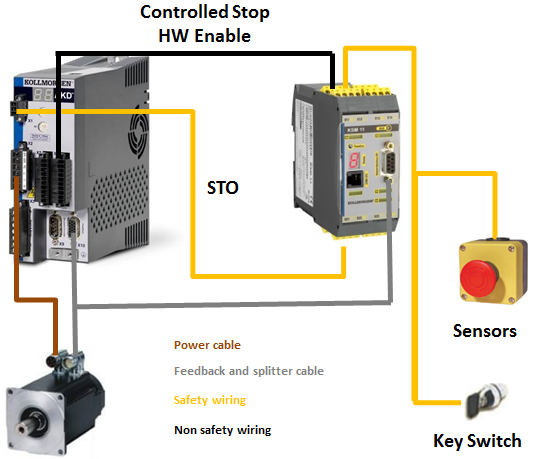
Safe Torgue Off (STO)
The STO safety implementation on the AKD is certified (AKD-x04807 in process). The safety circuit implementation used for the safety function "Safe Torque Off" in the drive is suited for SIL2 according to IEC 61508-2 and PLd/CAT3 according to ISO 13849-1. With AKD-x04807 drives SIL3/PLe is possible if both STO-Enable inputs and the corresponding STO-Status signals are used.
See Safety Concept AKD for more information about STO.
AKD-x003 to to AKD-x024
An additional digital inut (STO) releases the power output stage of the drive as longs as a 24V signal is applied to this input. If the STO input goes open-circuit, then power will no longer be supplied to the motor, and the drive will lose all torque and coast to a stop.
Note: The input is not compatible with IEC 61131-2. You can thus achieve a category 0 stop by using the STO input without switching to a mains contactor.
AKD-x048
Two additional digital inputs (STO-Enable1 and STO-Enable2) release the power ooutput stage of the drive as long as a 24V signal is applied to these inputs. If on e of the STO inputs goes open-circuit, then power will no longer be supplied to the motor, and the five will lose all torque and coast to a stop.
Note: The input is not compatible with IEC 61131-2. You can thus achieve a category 0 stop by using the STO input without switching to a mains contactor.
Functional Description
When STO function (Safe Torque Off) is not needed, then STO-Enable must be connected directly with +24V. The STO function is then bypassed and cannot be used.
If the STO function is in use, then the STO-Enable must be connected to the output of a security control or a safety relay, which at least meets the requirements of PLd, CAT3 according to ISO 13849.
Prohibited Use
The STO function must not be used if the drive is to be made inactive for:
- Cleaning, maintenance, and repair operations, long inoperative periods. In such cases, the entire system should be disconnected from the supply and secured (main switch).
- Emergency-Off situations: In an Emergency-Off situation the main contactor is switched off (by the Emergency-Off button).
Safety Characteristic Data
The subsystems (AKD) are described with the following characterstic data:
AKD-x003 up to AKD-x024
| Function | Operation Mode | ISO 13849-1 | IEC 61508-2 | PFH [1/h] | Tm [Years] | SFF [%] |
| STO | single channel | PLd, CAT3 | SIL2 | 0 | 20 | 100 |
AKD-x048
| Function | Operation Mode | ISO 13849-1 | IEC 61508-2 | PFH [1/h] | Tm [Years] | SFF [%] |
| STO | single channel | PL d, CAT2 | SIL2 | 1.88E-07 | 20 | 89 |
| STO | dual channel | PL d, CAT3 | SIL2 | 5.64E-09 | 20 | 87 |
| STO | dual channel with periodic testing | PL d, CAT4 | SIL3 | 5.64E-09 | 20 | 87 |
KSM Examples
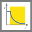
Safety Function: STO

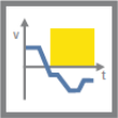
Safety Function: SLS with speed monitoring