


Encoders are the most widely applicable feedback devices for high-precision servo systems because they deliver high-resolution position data with reliable control when properly selected and protected from noise.
This post explains how to choose and apply the right feedback devices for your motion system:
- Compare linear, rotary, and sine encoders by resolution, accuracy, speed, and cost as feedback devices
- Match encoder type to application needs (travel length, inertia, smooth low-speed motion) using feedback devices
- Reduce EMI/RFI issues with robust signaling and conditioning for cleaner feedback devices
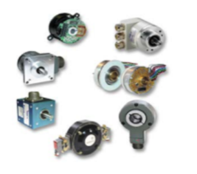
Encoders: The High-Resolution Feedback Choice
Encoders are characterized under three basic categories: rotary or linear; incremental or absolute; and whether the signal is generated by optical, magnetic or contacting means. Noncontacting encoders are more common than contacting devices, and in this category we’ll focus on optical encoders, which are more common and precise than magnetic.
When optical encoders first appeared, they were praised for their ability to offer high accuracy in both low and high-speed applications. However, early versions were sometimes viewed as unreliable. Much of the problem was simply due to misapplication: When installed on heavy industrial equipment, vibration and temperature sometimes took a toll on fragile electronics and glass encoding disks.
Today’s versions are more rugged, with better-protected electronics and optics. Even so, most manufacturers still recommend selecting optical encoders for lighter industrial applications, where they are exposed to temperatures below 90ºC and vibration below 20 G.
Linear Encoders
Linear encoders contain a linear track and a read head, and are usually used with systems that track linear movement, such as X-Y stages and position tables. The linear track can range in length from a few inches to several feet. It is etched with graduations that are scanned by the read head as motion components move. The read head detects multiple channels to provide position and direction data. Encoders with sinusoidal outputs use additional interpolation circuitry to electronically improve resolution.
For equipment that requires particularly high resolution, linear encoders are the best choice in their class. Resolutions to 0.1 microns are common, with some systems offering resolution to 20 nanometers. Accuracy, typically 20 microns per meter, may decrease linearly over the travel distance of the track. However, this can be compensated for with slope error correction to bring any error below 5 microns per meter.
Machines operating at high speeds use linear encoders because these devices typically work at higher speeds than other feedback devices. The primary factor that can potentially limit speed is whether or not the electronic counting circuitry can keep pace.
Optical Rotary Encoders
Optical rotary encoders consist of a light source, a rotating code disc and a light detector. The disc has either slits or graduations that divide it into equally spaced areas of dark and light. These markings often are referred to as lines, hence the unit of measure: lines per revolution (LPR). This measurement indicates an encoder’s resolution or granularity.
Accuracy for encoders is defined as plus (+) or minus (–) a given number of lines or counts. It is important to note that accuracy and resolution are different attributes, although they are often related. With encoders, as count resolution increases, the accuracy within a specific number of counts increases as well. This is in contrast to resolvers, where increasing resolution through more interpolation — 16 bits versus 12 bits for example — does not increase accuracy. In fact, it is quite common for resolver systems to have 100 times lesser accuracy than resolution.
As the connected components of an encoder rotate, the light detector registers the on-off pattern of the light passing through the disc. The detector converts this on-off pattern into an electronic digital signal that looks like square waves. Typically, two rows of slits or markings are offset by one half of their width or one quarter of a complete cycle (90 electrical degrees), generating two electrical signals known as Channel A and Channel B. This offset allows the control to determine the direction of the shaft rotation — an important piece of information for the drive during start up and essential information for servo systems providing bidirectional motion.
Instead of using only two channels, some encoders use additional channels to track shaft position or help with noise immunity. These channels include what is referred to as the index and complement channels. Another means of tracking shaft position is to add a commutation or Hall-equivalent channel. These represent alignment to the A-phase, B-phase and C-phase (also known as U, V and W) back EMF of the motor.
Depending on how the encoder counts the A and B channels, resolution can increase fourfold. This capability arises when the counting circuit tracks both the falling and rising edges of both signals, also referred to as quadrature detection. Increasing resolution increases system repeatability. High resolution also enables higher gain for position and velocity loops, ensuring full system bandwidth.
Encoder resolutions of 50 to 5,000 lines per revolution are standard among most vendors, but line counts to 100,000 are available. In high-accuracy applications, system accuracy is affected by errors from other sources such as lead-screw cumulative error, thermal expansion or nut backlash. Linear encoders can overcome these challenges.
Sine Encoders
Sine encoders are at the high-cost, high-accuracy, high-precision end of the feedback device spectrum. They are similar to incremental encoders, except that the A and B data channels are typically sent to the controller as one-volt peak-to-peak sine waves instead of square waves.
The benefit is that these devices can interpolate each complete sine wave, increasing system resolution and giving more information to the velocity controller. This reduces truncation and quantization errors, allowing higher loop gains.
Sine encoders can achieve over 2 million counts per revolution, or about 0.62 arcseconds of resolution. Such capability is well suited to applications that require high precision or have high-inertia loads.
Like other encoders, sine encoders may also have commutation tracks, Hall-emulation tracks, or auxiliary sinusoidal channels called C and D, which provide absolute position within one revolution. The C and D channels are similar to the sine and cosine signals used in resolvers.
A variation of sine encoders is the multiple-turn sine encoder. Multi-turn versions are implemented using an internal mechanical gearbox, Wiegand sensor or battery backup mechanism. This provides absolute positioning over many revolutions of the device. These encoders can provide up to 8192 steps per revolution and up to 8192 shaft revolutions, providing a total of 26 bits of absolute resolution before interpolation.
Sine encoders offer high precision, resolution and accuracy for applications ranging from high-speed registration to film coating and web control. Sine encoders also fit low-speed operations where smooth rotation is critical. They help motion systems achieve high gains, superior stiffness and position accuracy in rotary tables, indexing assembly machines and roll drives.
Quieting Noise
Feedback devices can output electrical or optical signals. One advantage of using optical transmission lines for feedback signals is that they are immune to high-noise or electromagnetic interference/radio-frequency interference (EMI/RFI) environments that could otherwise interfere with clean signals and distort data sent to the drive, compromising its ability to provide high-quality position, speed and torque control.
When sending signals electrically, amplifiers or signal-conditioning devices may be needed to modify noisy signals. Newer feedback devices use IC chips to convert and interpolate signals to more robust waveforms that aren’t corrupted by noise and that won’t diminish as they propagate through the cable to the drive.
Learn more
Be sure to read all three of our Feedback Devices blog posts high-level selection criteria, as well as Hall-effect sensors and resolvers, in addition to the linear, rotary and sine encoders we’ve covered here to become conversant in this crucial motion topic. And feel free to contact a Kollmorgen engineer to discuss your specific application and get recommendations for the best servo-loop technology to suit your needs.


