


 Home >
 Knowledge Base >
 FAQs >
 Downloads >
MultiFeedback
Valid for S300, S400, S600, S700
The servo amplifiers support a lot of different feedback devices. Depending on the feedback type the data are transmitted digitally or analog to the servo amplifier. KOLLMORGEN servo amplifiers can evaluate up to three feedbacks at the same time.
Feedback functionality must be defined via the setup software.
- FBTYPE adjustable on DRIVEGUI screen page FEEDBACK, primary feedback (motor feedback)
- EXTPOS adjustable on DRIVEGUI screen page POSITION CONTROL, secondary feedback for external position feedback
- GEARMODE adjustable on DRIVEGUI screen page ELECTR. GEARING, encoder master for electronic gearing
Scaling and other settings must be done there as well.
Wiring Variants
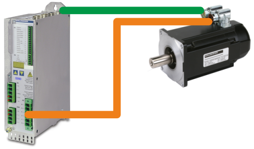
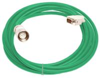
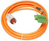
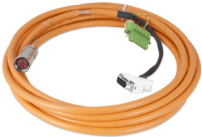
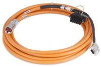
Dual cable connection
Motor power and feedback system are connected with two cables. Motor Holding brake lines are connected via additional lines in the motor power cable. The motor temperature sensor (PTC or NTC resistor) built into the motor winding, is connected to the servo amplifier via the feedback cable.
| S300 | S700 |
|---|---|
 |
 |
  |
 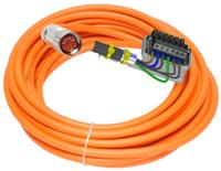 |
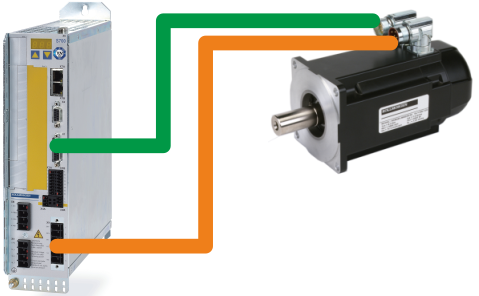
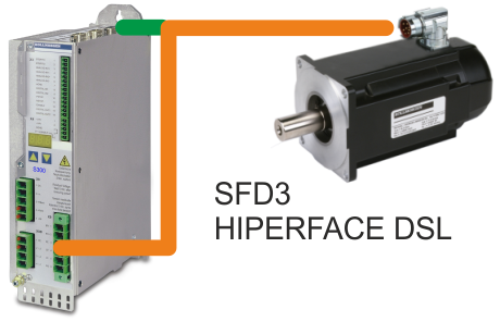
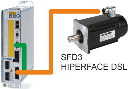
Single Cable Connection
Available from October 2016
Motor power and feedback system are connected with one hybrid cable. Motor Holding brake lines are connected vie additional lines in the hybrid cable. With the digital feedback systems SFD3 or HIPERFACE DSL, the motor temperature sensor (PTC or NTC resistor) built into the motor winding is evaluated in the Encoder and the temperature value is transmitted digitally to the servo amplifier.
The hybrid cable is split close to the servo amplifier. Connector X1 (Encoder connector) includes a Splitter Adapter.
| S300 (from HWR 4.20) | S700 (from HWR 2.30) |
|---|---|
 |
 |
 |
 |
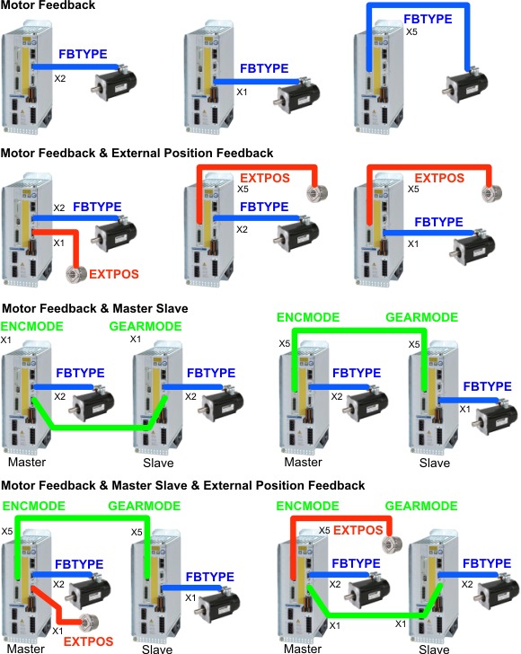
Possible Feedback Configurations
The graphic below just shows some of the possible configurations. Examples with S700 drives and AKM motors. Connectors X1 and X2 are in the standard device, X5 is located on the Expansion card POS-IO or Expansion card POS-IO-Monitor.
Feedback Systems
Parameters
| Parameters | |||
|---|---|---|---|
| Feedback | FBTYPE (Primary) |
EXTPOS (Secondary) |
GEARMODE |
| ResolverFeedback (2-36 poles) | 0 | - | - |
| Smart Feedback Device SFD, four lines | - | - | - |
| Smart Feedback Device SFD3, two lines | 36 | - | - |
| Absolute Encoder with BiSS B (5V, sincos) | 23 | - | - |
| Absolute Encoder with BiSS B (12V, sincos) | 24 | - | - |
| Absolute Encoder with BiSS B (5V, digital) | 20 | 11 | 11 |
| Absolute Encoder with BiSS B (12V, digital) | 22 | 11 | 11 |
| Absolute Encoder with BiSS C (5V, digital,m Renishaw) | 334) | 124) | 124) |
| Absolute Encoder with EnDat 2.1 with analog signals, SinCos | 4,21 | 8 | 8 |
| Absolute Encoder with EnDat 2.2 | 32,34 | 13 | 13 |
| Absolute Encoder with Hiperface | 2 | 9 | 9 |
| Absolute Encoder with Hiperface DSL | 35 | - | - |
| Safety Absolute Encoder with Hiperface | 2 | 9 | 9 |
| Sine Encoder without data channel | 1,3,7,8 | 6,7 | 6,7 |
| Sine Encoder with Hall Sensors | 5,6 | - | - |
| Sine Encoder with SSI | 263) (S300:283)) | - | - |
| Incremental Encoder AquadB (5V) | 133),17,193), 27,31,30 | 10,30 | 3,10,30 |
| Incremental Encoder AquadB (24V) | 12,16 | 2 | 2 |
| Incremental Encoder with Hall (5V) | 153),18 | - | - |
| Incremental Encoder with Hall (24V) | 14 | - | - |
| Absolute Encoder with SSI | 93),253) | 53),253) | 5,25 |
| Hall Sensors | 11 | - | - |
| Step Direction interface (5V) | - | 4,27 | 4,27 |
| Step Direction interface (24V) | - | 1 | 1 |
| Sensorless (without Feedback) | 10 | - | - |
| DRIVE-CLiQ | - | - | - |
Drives
| Drives | ||||||
|---|---|---|---|---|---|---|
| Feedback | S300 | S400 | S600 | FBTYPE | AKD Drive | |
| ResolverFeedback (2-36 poles) | P | P | P | P | 40 | P |
| Smart Feedback Device SFD, four lines | - | - | - | - | 41 | P |
| Smart Feedback Device SFD3, two lines | P | - | - | P | - | P |
| Absolute Encoder with BiSS B (5V, sincos) | P | P | P | P | 32 | P |
| Absolute Encoder with BiSS B (12V, sincos) | P | - | P | P | - | - |
| Absolute Encoder with BiSS B (5V, digital) | P S | - | - | P S | - | - |
| Absolute Encoder with BiSS B (12V, digital) | P S | - | - | P S | - | - |
| Absolute Encoder with BiSS C (5V, digital,m Renishaw) | P4) S4) | - | - | P4) S4) | - | P4) |
| Absolute Encoder with EnDat 2.1 with analog signals, SinCos | P S | P | P | P S | 30 | P |
| Absolute Encoder with EnDat 2.2 | P S | - | - | P S | 31 | P S |
| Absolute Encoder with Hiperface | P S | P | P | P S | 33 | P |
| Absolute Encoder with Hiperface DSL | P | - | - | P | - | x |
| Safety Absolute Encoder with Hiperface | P S | P | P | P S | ||
| Sine Encoder without data channel | P S | P S | P S | P S | 21 | P |
| Sine Encoder with Hall Sensors | P | P | P | P | 20 | P |
| Sine Encoder with SSI | P | - | - | P | - | - |
| Incremental Encoder AquadB (5V) | P S | P S | P S | P S | 11 | P S |
| Incremental Encoder AquadB (24V) | P S | P S | P S | P S | - | S |
| Incremental Encoder with Hall (5V) | P | P | P 1) | P | 10 | P |
| Incremental Encoder with Hall (24V) | P | P | P 1) | P | - | - |
| Absolute Encoder with SSI | P S 2) | S | S | P S | - | - |
| Hall Sensors | P | - | P 1) | P | - | - |
| Step Direction interface (5V) | S | S | S | S | - | S |
| Step Direction interface (24V) | S | S | S | S | - | S |
| Sensorless (without Feedback) | P | P | P | P | - | - |
| DRIVE-CLiQ | - | - | - | - | ||
Motors
| Motors | ||||||
|---|---|---|---|---|---|---|
| Feedback | AKM | AKMH | VLM | DBL/DBK | CDDR | KBM |
| ResolverFeedback (2-36 poles) | x | x | x | x | ||
| Smart Feedback Device SFD, four lines | x | x | x | |||
| Smart Feedback Device SFD3, two lines | x | x | ||||
| Absolute Encoder with BiSS B (5V, sincos) | x | x | ||||
| Absolute Encoder with BiSS B (12V, sincos) | ||||||
| Absolute Encoder with BiSS B (5V, digital) | ||||||
| Absolute Encoder with BiSS B (12V, digital) | ||||||
| Absolute Encoder with BiSS C (5V, digital,m Renishaw) | ||||||
| Absolute Encoder with EnDat 2.1 with analog signals, SinCos | x | x | x | x | ||
| Absolute Encoder with EnDat 2.2 | ||||||
| Absolute Encoder with Hiperface | x | x | ||||
| Absolute Encoder with Hiperface DSL | x | x | ||||
| Safety Absolute Encoder with Hiperface | x | |||||
| Sine Encoder without data channel | ||||||
| Sine Encoder with Hall Sensors | ||||||
| Sine Encoder with SSI | ||||||
| Incremental Encoder AquadB (5V) | ||||||
| Incremental Encoder AquadB (24V) | ||||||
| Incremental Encoder with Hall (5V) | x | x | x | |||
| Incremental Encoder with Hall (24V) | ||||||
| Absolute Encoder with SSI | ||||||
| Hall Sensors | x | x | ||||
| Step Direction interface (5V) | ||||||
| Step Direction interface (24V) | ||||||
| Sensorless (without Feedback) | ||||||
| DRIVE-CLiQ | x | |||||
P = primary Feedback
S= secondary Feedback
1) S601-620 with Hall dongle
2) via X5 only
3) switch on supply voltage on X1 for encoder: set ENCVON to 1
4) Hengstler BiSS C encoders are not supported, Renishaw encoders are supported.
Accuracy
Accuracy of the feedback systems is various.
- S300 (HWR <4.0), S400, S600: please refer to page Feedback Accuracy.
- S300 (HWR >=4.00), S700: please refer to page Feedback Accuracy S700.
Safety characteristic data
The feedback systems have different MTTFD values. This leads to different safety evaluation. See page Safety Characteristic Data.
Permitted cable length
The adequate 5V supply for the feedback devices is usually monitored/adjusted with 2 sense lines. Depending on the encoder manufacturer, the connections + 5V => sense+ and 0V => sense- is implemented in the encoder itself or must be fitted in the connector. In particular for long cables the function of feedback depends on correctly connected sense lines.
| S300 | S400 | S600 | S700 | AKD | |
|---|---|---|---|---|---|
| Resolver | 100m | 25m | 100m | 100m | 100m |
| SFD | - | - | - | - | 100m |
| SFD3 | 25m | - | - | 25m | |
| Absolut Encoder with BiSS | 50m | 50m | 50m | 50m | 50m |
| Absolut Encoder with EnDat | 50m | 25m | 50m | 50m | 50m |
| Absolut Encoder with Hiperface | 50m | 25m | 50m | 50m | 50m |
| Hiperface DSL | 25m | - | - | 25m | |
| Absolut Encoder with SSI | 50m | 50m | 50m | 50m | - |
| Sine Encoder | 50m | 50m | 50m | 50m | 25m |
| Sine Encoder with Hall | 25m | 25m | 25m | 25m | 25m |
| Sine Encoder with SSI | - | - | - | 50m | - |
| Incremental Encoder 5V | 50m | 50m | 50m | 50m | 25m |
| Incremental Encoder 24V | 25m | 25m | 25m | 25m | - |
| Incremental Encoder with Hall | 25m | 25m | 25m | 25m | 25m |
| Hall Sensors | 25m | - | 25m | 25m | - |
| Step Direction interface | 25m | 25m | 25m | 25m | 25m |
Termination resistors
Overview of the termination resistors for RS485 and differential analog inputs:
| S300 | S400 | S600 | S700 | AKD | ||||
|---|---|---|---|---|---|---|---|---|
| HWR 2/3 | HWR 4 | X1 | X5 | X10 | ||||
| SFD, SFD3 | - | - | - | - | - | - | 0 | |
| Sine Encoder | 0 | 0 | 0 | 0 | 0 | - | ext | |
| Absolut Encoder with BiSS analog | 0 | 0 | 0 | 0 | 0 | - | 0 | |
| Absolut Encoder with BiSS digital | 0 | 0 | - | - | 0 | - | - | |
| Absolut Encoder with EnDat 2.1 | 0 | 0 | 0 | 0 | 0 | - | 0 | |
| Absolut Encoder with EnDat 2.2 | - | 0 | - | - | 0 | 0 | ||
| Absolut Encoder with Hiperface | 0 | 0 | 0 | 0 | 0 | - | 0 | |
| Absolut Encoder with SSI | ext | 0 | ext | ext | 0 | ext | - | |
| Incremental Encoder 5V 1.5MHz | ext | Channel A: ext Channel B: 0 |
ext | ext | Channel A: ext Channel B: 0 |
ext | 0 | |
| Incremental Encoder 5V 350 kHz | 0 | 0 | - | - | 0 | - | - | |
- = not available
0 = no ext. resistor required
ext = ext. resistor required
